Battery pack heat dissipation structure and device

A technology of heat dissipation structure and battery pack, applied in secondary batteries, circuits, electrical components, etc., can solve problems such as temperature rise, and achieve the effect of solving excessive temperature rise and improving heat dissipation effect

Pending Publication Date: 2019-09-10
TINECO APPLIANCES CO LTD
View PDF0 Cites 0 Cited by
  • Summary
  • Abstract
  • Description
  • Claims
  • Application Information

AI Technical Summary

Problems solved by technology

[0004] The technical problem to be solved by the present invention is to provide a battery pack heat dissipation structure and its device in view of the deficiencies of the prior art. By opening vents on the traditional battery pack that communicate with the fan and the outside air respectively, the built-in cooling device is used to The fan is used as the power source of the air flow, and the hollow components of the device are used as the ventilation duct, so that the fan can also drive the air circulation inside the battery pack while completing its own tasks, which solves the problem of the temperature of the battery pack and the parts around the battery in battery products. The problem of too high rise makes the battery pack and the parts around the battery have a good heat dissipation effect, so that a larger capacity battery can be selected when designing the whole machine

Method used


Image

  • Battery pack heat dissipation structure and device
  • Battery pack heat dissipation structure and device
  • Battery pack heat dissipation structure and device

Examples


Embodiment 1

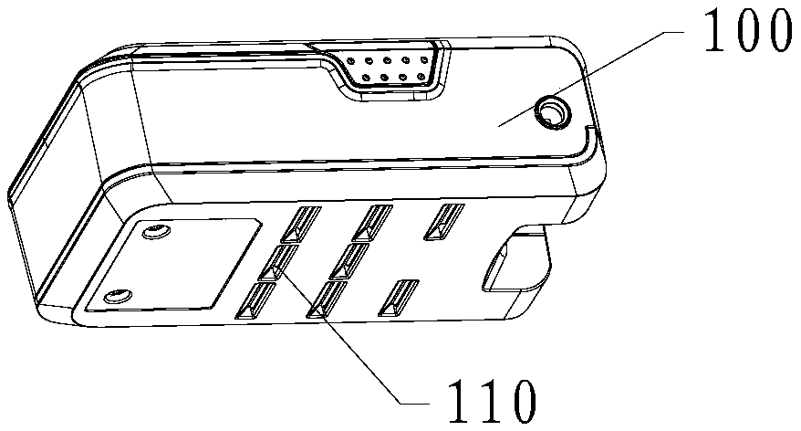
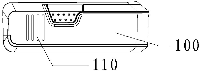
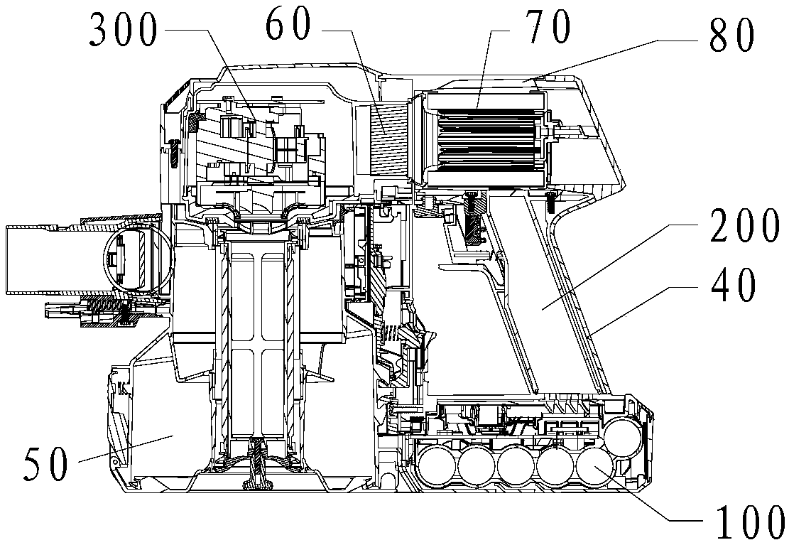
[0030] image 3 It is a sectional view of Embodiment 1 of the present invention. Such as image 3 As shown, in this embodiment, the device is a vacuum cleaner, the battery pack 100 is arranged under the handle 40 of the vacuum cleaner, the fan 300 is a motor for providing suction in the vacuum cleaner, and the ventilation duct 200 is a hollow vacuum cleaner. A part of the vents 110 communicates with the handle 40 , and the other part directly communicates with the air outside the battery pack 100 .

[0031] When the vacuum cleaner is working, the dust-laden air enters the dust storage chamber 50 of the vacuum cleaner from the suction port of the vacuum cleaner under the suction provided by the motor. After being processed by the separator, most of the dust remains in the dust storage chamber 50, and the air passes The motor then blows to the inside of the battery pack through the ventilation duct 200 to take out the heat in the battery pack, thereby reducing the temperature ...

Embodiment 2

[0035] Figure 4 It is a sectional view of Embodiment 2 of the present invention; Figure 5 for Figure 4 Partial enlarged view of A. Such as Figure 4 and Figure 5 As shown, similar to Embodiment 1, the device described in this embodiment is a vacuum cleaner, the battery pack 100 is arranged under the handle 40 of the vacuum cleaner, and the fan 300 is a motor for providing suction in the vacuum cleaner, which is different from Embodiment 1 Notably, in this embodiment, the ventilation duct 200 is a hollow shell between the dust storage chamber 50 of the vacuum cleaner and the battery pack 100 . Specifically, the dust storage chamber 50 is provided with an air intake hole 501 at the position facing the battery pack 100, and correspondingly, a part of the vent 110 is provided on the side of the battery pack 100 facing the dust storage chamber 50, and the Part of the vent 110 communicates with the air inlet 501 on the dust storage chamber 50 through the hollow shell, that ...

Embodiment 3

[0039] Figure 6 It is a structural schematic diagram of Embodiment 3 of the present invention; Figure 7 It is a sectional view of Embodiment 3 of the present invention. Such as Figure 6 and Figure 7 As shown, in this embodiment, the device is an electric screwdriver, the battery pack 100 is arranged under the handle of the electric screwdriver, the fan 300 is a motor that rotates the screwdriver in the electric screwdriver, and the ventilation duct 200 is an electric screwdriver. The hollow shell between the screwdriver battery pack 100 and the motor, the plurality of vents 110 are partly communicated with the hollow shell, and partly communicated directly with the air outside the battery pack 100 .

[0040] When the electric screwdriver is working, the motor drives the screwdriver to rotate, and the air generated passes through the ventilation duct 200, enters the battery pack 100, and then flows to the outside air through the vent 110, thereby taking out the heat in t...


PUM


Abstract

A battery pack heat dissipation structure and device are provided. The battery pack heat dissipation structure includes a battery pack (100) which is provided with multiple air vents (110) in the shell thereof. One part of the air vents are communicated with a fan (300) through a ventilation duct (200), and the other part of the air vents are directly communicated with the air outside the batterypack. In the invention, air vents communicated with a fan and air vents communicated with the outside air are arranged in a traditional battery pack, the fan in the device is used as a power source ofthe airflow, and a hollow assembly of the device is used as a ventilation duct, so that the fan can drive the airflow in the battery pack while completing its own task. The problem of excessive temperature rise of the battery packs of battery products and the parts around batteries is solved, and a good heat dissipation effect is achieved for battery packs and parts around batteries. Batteries with larger capacity can be selected in the design of the whole machine.

Description

technical field [0001] The invention relates to a heat dissipation structure of a battery pack and a device thereof, belonging to the technical field of small household appliance manufacturing. Background technique [0002] In the development of modern technology, battery products have been integrated into the current product design, and the proportion of battery products in small household appliances is also increasing. Although battery products bring convenience and quickness to people's life, if the battery product explodes, it will bring considerable harm. Fundamentally speaking, the explosion of battery products is caused by the heat accumulated inside the battery not dissipating, which leads to the overheating of the battery core and surrounding parts, which causes combustion. [0003] In the existing technology, the battery cannot be well dissipated. Under this limitation, the selected battery capacity is generally not too large, so as to ensure that the battery and ...

Claims


Application Information

Patent Timeline
Patent Type & Authority Applications(China)
IPC IPC(8): H01M10/613H01M10/6235H01M10/655H01M10/6556H01M10/6563
CPCH01M10/613H01M10/6235H01M10/655H01M10/6556H01M10/6563A47L9/2884A47L9/32Y02E60/10
Inventor 许飞翔刘凯任怀强
Owner TINECO APPLIANCES CO LTD
Why Eureka
Try Eureka