Common-mode voltage suppression system

A common-mode voltage and common-mode capacitor technology, applied in the field of common-mode voltage suppression system, can solve the problems of three-phase four-wire or three-phase five-wire power supply, AC and DC side common-mode interference, etc.

Pending Publication Date: 2019-09-10
GLOBAL ENERGY INTERCONNECTION RES INST CO LTD +1
View PDF0 Cites 1 Cited by
  • Summary
  • Abstract
  • Description
  • Claims
  • Application Information

AI Technical Summary

Problems solved by technology

[0004] In order to solve the problems existing in the prior art that the existing system cannot provide three-phase four-wire or three-phase five-wir

Method used


Image

  • Common-mode voltage suppression system

Examples


Embodiment 1

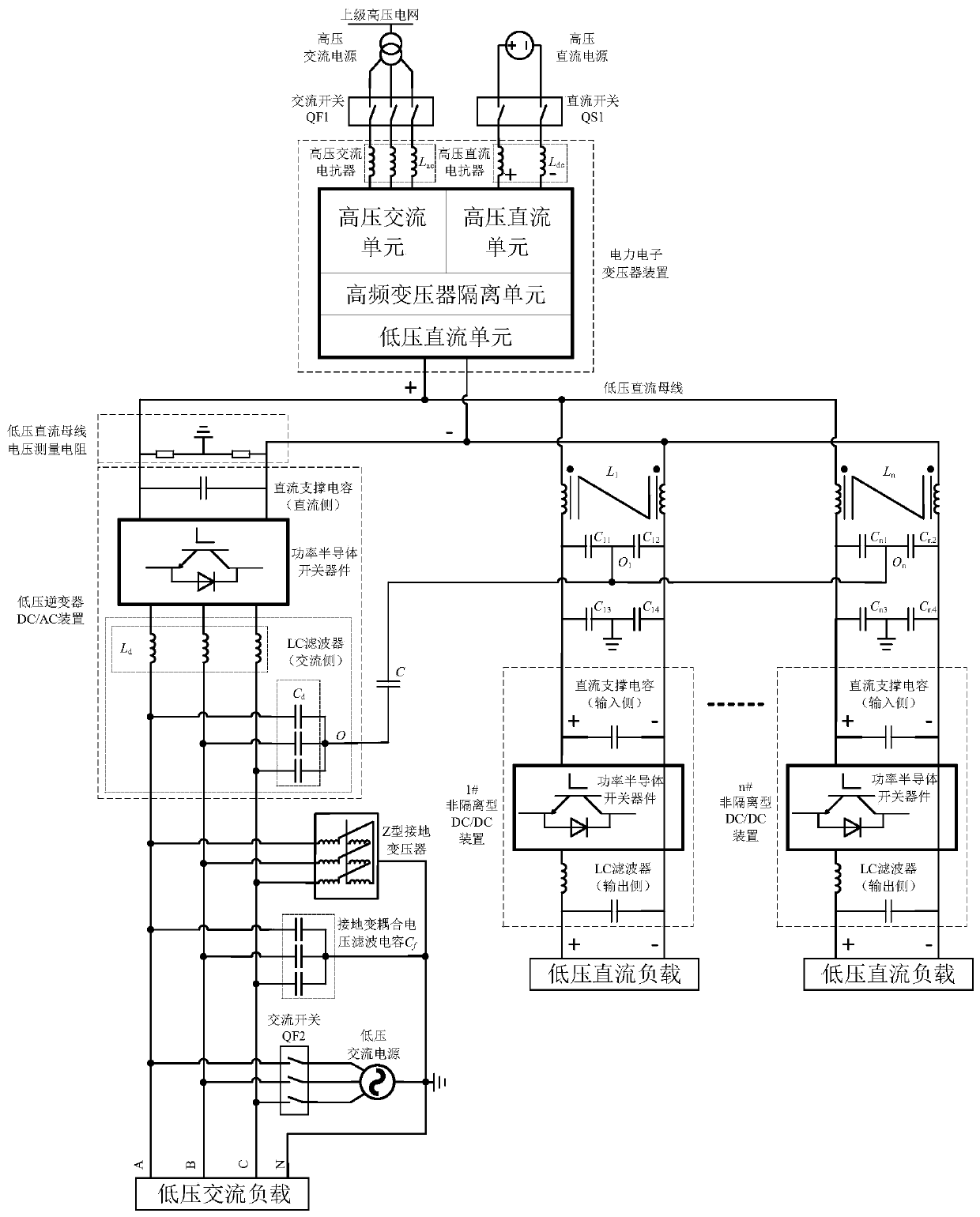
[0062] This embodiment provides a common-mode voltage suppression system, a schematic diagram of the common-mode voltage suppression system, as shown in figure 1 As shown, it usually consists of a power electronic transformer device, an inverter DC / AC device and a DC / DC device.

[0063] The power electronic transformer device in the figure usually consists of a high-voltage AC unit, a high-voltage DC unit, a high-frequency transformer isolation unit, a low-voltage DC unit, and a high-voltage AC reactor L ac , HVDC smoothing reactor L dc and other components; the power electronic transformer passes through the reactor L ac , The AC switch QF1 is connected to the high-voltage AC power supply, and through the smoothing reactor L dc1. The DC switch QS1 is connected to the high-voltage DC power supply; the low-voltage DC unit is connected to the low-voltage DC bus. The power electronic transformer is responsible for the transformation of the voltage level and the transformation ...

Embodiment 2

[0069] This embodiment provides a common-mode voltage suppression system, the system comprising:

[0070] Power electronic transformers, low-voltage DC buses, low-voltage inverter DC / AC devices and non-isolated DC / DC devices;

[0071] The input end of the power electronic transformer is connected to the medium and high voltage grid, and the output end is connected to the low-voltage DC bus;

[0072] The input end of the low-voltage inverter DC / AC device is connected to the low-voltage DC bus, and the output end is connected to a low-voltage AC load;

[0073] The input end of the non-isolated DC / DC device is connected to the low-voltage DC bus in parallel, and the output ends are respectively connected to the low-voltage DC load;

[0074] The output side of the low-voltage inverter DC / AC device is connected to the input side of the non-isolated DC / DC device to form a low-impedance loop of common-mode voltage;

[0075] The medium and high voltage power grid is a DC medium and ...


PUM


Abstract

Disclosed is a common-mode voltage suppression system. The common-mode voltage suppression system is characterized in that the input end of a power electronic transformer in the system is connected with a medium-high-voltage power grid, while the output end of the power electronic transformer is connected with a low-voltage direct-current bus; the input end of a low-voltage inverter DC/AC device is connected with the low-voltage direct-current bus while the output end is connected with a low-voltage alternating-current load; the input end of a non-isolation type DC/DC device is connected to the low-voltage direct-current bus in parallel while the output end is connected with a low-voltage direct-current load separately; and the output side of the low-voltage inverter DC/AC device is connected with the input side of the non-isolation type DC/DC device to form a low-impedance loop of the common-mode voltage. According to the scheme, the low-impedance loop of the common-mode voltage is constructed at the output side of the low-voltage inverter DC/AC device and the input side of the non-isolation type DC/DC device, so that the direct current side to alternating current side common-modevoltage can be suppressed effectively, and the problem that a non-isolated alternating-current and direct-current power supply circuit is too high in common-mode voltage to interfere a power supply process is solved.

Description

technical field [0001] The invention relates to the technical field of AC and DC power supply, in particular to a common-mode voltage suppression system. Background technique [0002] The AC-DC power supply system is the core part of the upcoming AC-DC distribution network in the future. It is responsible for the important role of power conversion (including voltage level conversion, frequency conversion, AC-DC power supply mode conversion, etc.) and power supply. Its core technology is power Electronic equipment technology. In actual application design, in order to increase the power density of equipment, reduce the manufacturing cost of equipment or in consideration of other design factors, usually the low-voltage AC side of equipment usually uses high-power three-phase three-wire non-isolated inverters to supply power to low-voltage AC loads , The low-voltage DC side of the equipment mostly uses high-power non-isolated DC / DC (DC / DC) converters to supply power to low-volt...

Claims


Application Information

Patent Timeline
IPC IPC(8): H02M1/12H02J5/00
CPCH02J5/00H02M1/12H02M1/123
Inventor 慕小斌邓占锋赵国亮陈国富李卫国王翔刘海军徐云飞才志远贾晓光周哲刘宗烨
Owner GLOBAL ENERGY INTERCONNECTION RES INST CO LTD
Why Eureka
Try Eureka