Hydraulic machine comprising a radial flow runner

一种水力机械、转轮的技术,应用在机械设备、水力发电、用于弹性流体的泵送装置的部件等方向,能够解决减小推力效果差等问题

Active Publication Date: 2019-09-10
VOITH PATENT GMBH
View PDF6 Cites 3 Cited by
  • Summary
  • Abstract
  • Description
  • Claims
  • Application Information

AI Technical Summary

Problems solved by technology

This geometry provides improved performance characteristics, but in many cases balance holes in the runner crown play a role in reducing thrust due to radial pumping effects in the runner crown space below the shaft flange less effective

Method used


Image

  • Hydraulic machine comprising a radial flow runner
  • Hydraulic machine comprising a radial flow runner
  • Hydraulic machine comprising a radial flow runner

Examples


Embodiment Construction

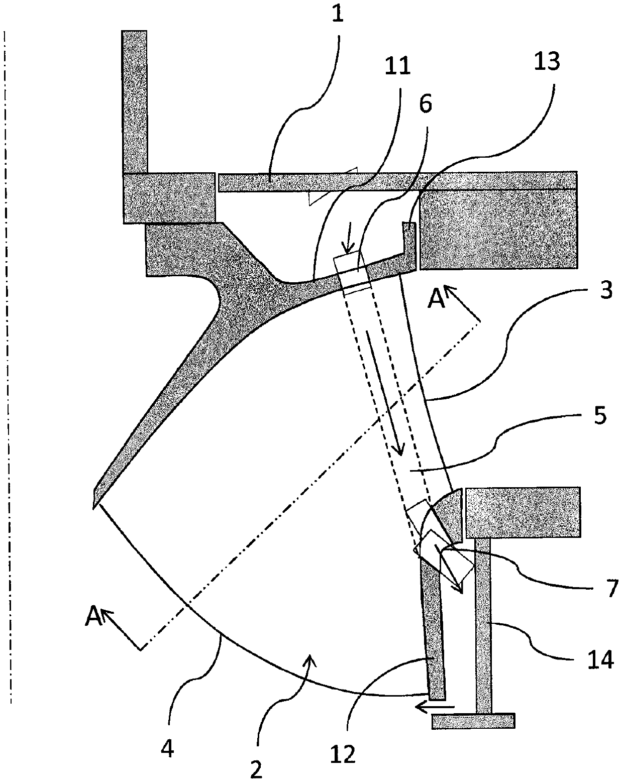
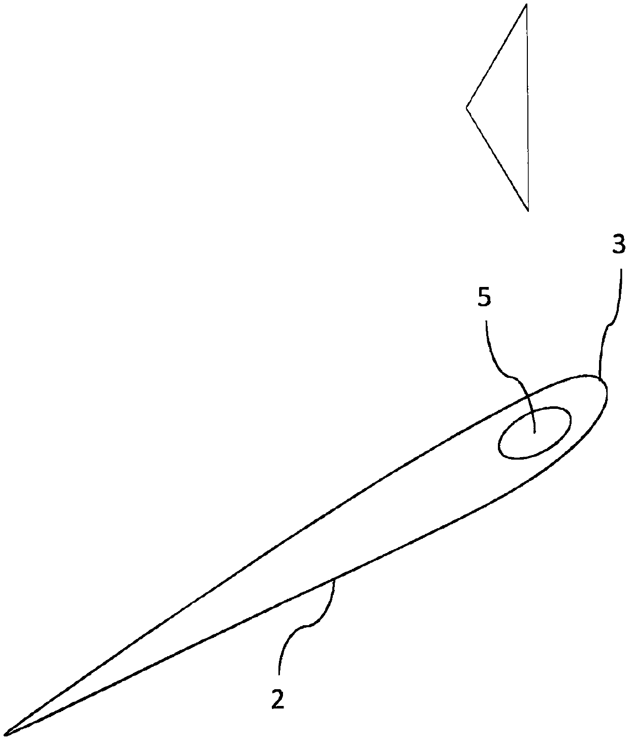
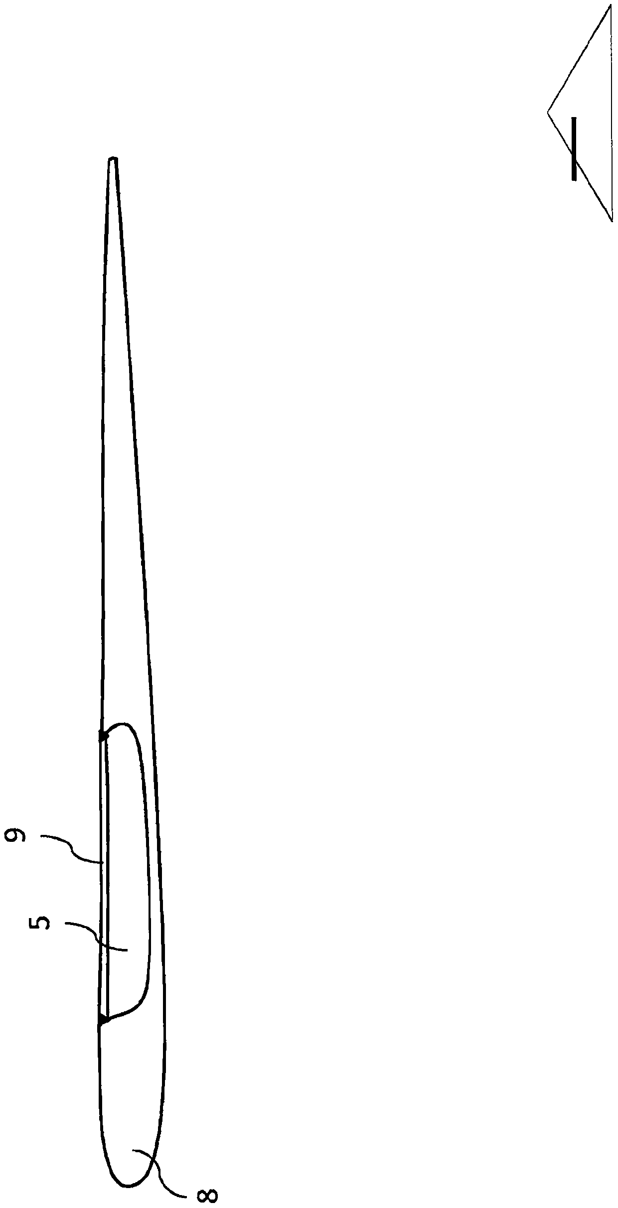
[0010] figure 1 A cross-sectional view of a hydraulic machine comprising a Francis-type runner according to the invention is schematically shown. The top cover is marked 1 and the bottom cover is marked 14 . The reel includes a reel crown, referenced 11 . The runner blades 2 extend between an upper crown 11 and a lower ring marked 12 . Blade 2 has two edges marked by 3 and 4 . Fluid entering the runner flows from edge 3 to edge 4 with the high pressure side adjoining edge 3 and the low pressure side adjoining edge 4 . Obviously, in pumping mode, the direction of fluid flow is reversed. The runner crown 11 comprises circumferentially positioned sealing means, referenced 13 . The sealing device 13 is explained as sealing the space between the top cover 1 and the upper crown 11 to prevent high-pressure water from entering. However, due to the imperfection of the seal, there will be a small amount of high-pressure water in the space above the upper crown 11 of the runner, re...


PUM


Abstract

A hydraulic machine comprising a runner of Francis type, a head cover and a lower cover is provided, whereas the runner comprises a low and a high pressure side, a crown, a band, a plurality of blades, whereas the crown comprises sealing means to seal the space between the crown and head cover against water from the high pressure side, whereas the runner comprises at least one passage being capable to drain high pressure leakage water passing the sealing means to the low pressure side, and the passage comprises an inlet aperture located in a portion of the crown which during operation is exposed to high pressure leakage water. The machine is characterized in that the passage is located within one of the blades and leads from the inlet aperture to the band, wherein the passage forms an opening leading to the space between the band and the lower cover.

Description

technical field [0001] The present invention generally relates to hydroelectric turbine or pump installations comprising radial flow runners of the Francis type. Background technique [0002] A hydraulic machine including a Francis type radial flow runner receives an axial thrust applied to the runner of the hydraulic machine. Since the seal between the runner and the high-pressure side of the water channel is not completely tight, pressurized water can enter the space between the top cover of the hydraulic machine and the runner crown, resulting in high axial thrust. In order to reduce the axial thrust, several concepts have been proposed in the prior art. One concept involves a balance pipe that discharges water passing through the seal to the low pressure side of the water channel (see eg US 1,820,150 to Moody). Another concept involves balancing holes in the runner crown leading to the hub of the runner or to the space between the blades of the runner (see eg US 4,086,...

Claims


Application Information

Patent Timeline
Patent Type & Authority Applications(China)
IPC IPC(8): F03B3/02F03B11/00
CPCF03B3/02F03B11/006Y02E10/20F04D3/005F04D29/168F03B3/125F05B2220/32
Inventor 斯图尔特·库尔森
Owner VOITH PATENT GMBH
Why Eureka
Try Eureka