Transmission control method of belt type continuously variable transmission

a transmission control and transmission technology, applied in the direction of gearing control, gearing elements, gearing, etc., can solve the problem of not being able to use a technique for measuring the friction coefficient of the radially outer portion of achieve the reduction of the friction coefficient between the pulley v surface and the metal belt, and the axial thrust of the driven pulley.

Active Publication Date: 2018-06-14
HONDA MOTOR CO LTD
View PDF0 Cites 0 Cited by
  • Summary
  • Abstract
  • Description
  • Claims
  • Application Information

AI Technical Summary

Benefits of technology

[0007]However, in Patent Document 1, there is disclosed a case in which the friction coefficient between the pulley V surface and the metal belt is reduced when a shape of a generatrix of the pulley V surface is curved but slippage is unlikely to occur at the radially outer portion of the pulley V surface even though the friction coefficient is reduced. However, if the friction coefficient of the radially outer portion of the pulley V surface can be chec

Problems solved by technology

Further, the technique disclosed in Patent Document 2 is effective as a technique for detecting a rotational direction of the metal belt with a high prec

Method used


Image

  • Transmission control method of belt type continuously variable transmission
  • Transmission control method of belt type continuously variable transmission
  • Transmission control method of belt type continuously variable transmission

Examples


Embodiment Construction

[0020]Hereinafter, an embodiment of the present invention will be described on the basis of FIGS. 1 to 6.

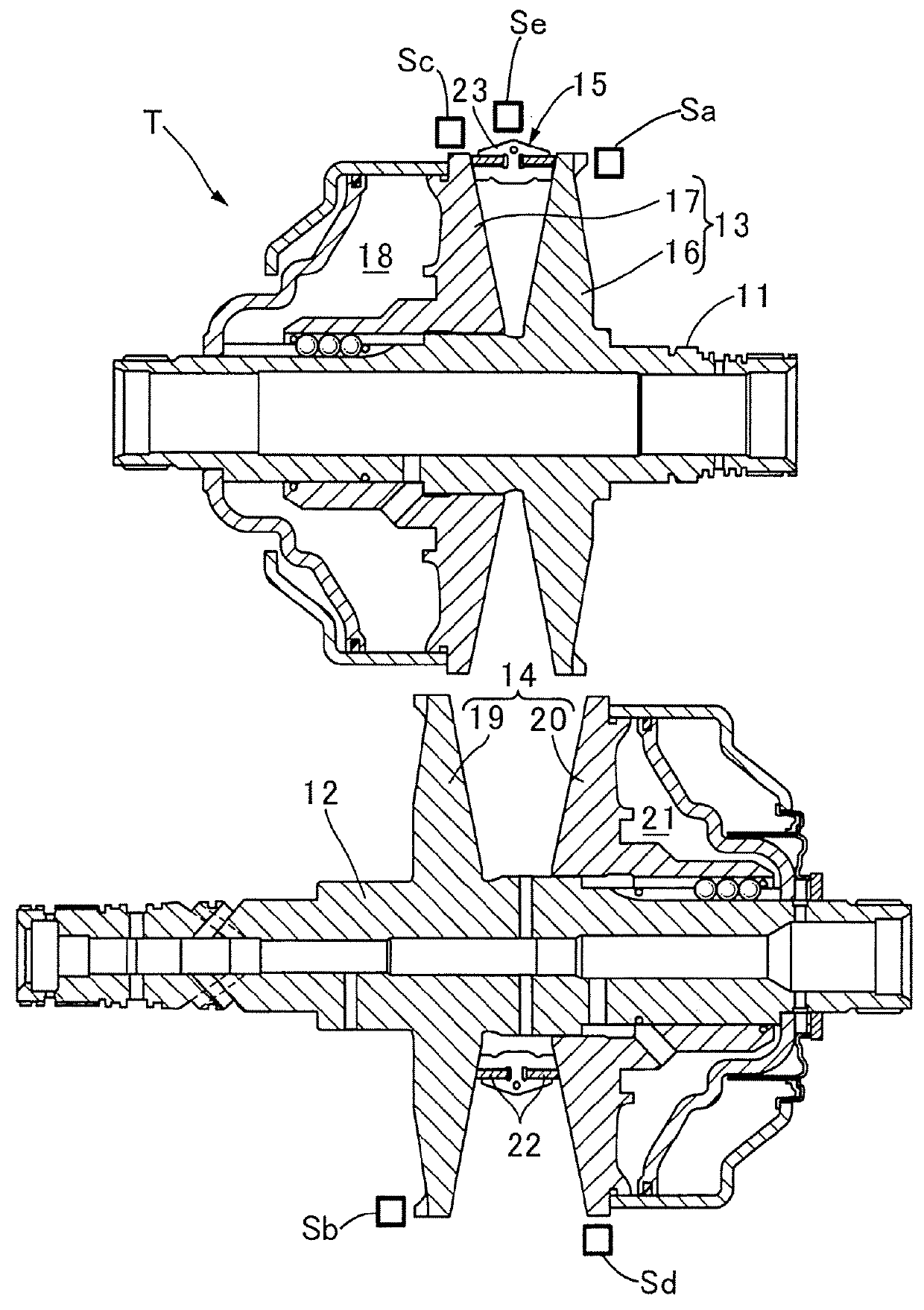
[0021]FIG. 1 illustrates a schematic constitution of a belt type continuously variable transmission T installed in an automobile, in which the belt type continuously variable transmission T includes a drive shaft 11 which is connected to an engine and a driven shaft 12 which is connected to drive wheels, and an endless metal belt 15 is wound on a drive pulley 13 provided on the drive shaft 11 and a driven pulley 14 provided on the driven shaft 12. The drive pulley 13 includes a fixed side pulley half 16 which is fixed to the drive shaft 11 and a movable side pulley half 17 which is capable of coming in contact with and being separated from the fixed side pulley half 16, and the movable side pulley half 17 is biased toward the fixed side pulley half 16 by a hydraulic pressure acting on an oil chamber 18. The driven pulley 14 includes a fixed side pulley half 19 which is fixed to t...


PUM


Abstract

In a first process, a tangential friction coefficient of a non-slippage side pulley of a drive pulley and a driven pulley is estimated from a tangential friction coefficient and a winding diameter of a slippage side pulley. In a second process, torque transmitted by a metal belt is calculated from the tangential friction coefficient and the winding diameter. In a third process, a required axial thrust of the non-slippage side pulley is calculated from the torque and the winding diameter. In a fourth process, the gear ratio is changed by reducing a ratio holding axial thrust of the non-slippage side pulley toward the required axial thrust. Therefore, the gear shifting can be performed merely by reducing the axial thrust of the non-slippage side pulley, and thus it is possible to improve the durability of the pulleys or the metal belt and to reduce a load of a hydraulic pump.

Description

CROSS-REFERENCE TO RELATED APPLICATION[0001]This application claims the priority benefit of Japan application serial no. 2016-239003, filed on Dec. 9, 2016. The entirety of the above-mentioned patent application is hereby incorporated by reference herein and made a part of this specification.BACKGROUND OF THE INVENTIONField of the Invention[0002]The present invention relates to a transmission control method of a belt type continuously variable transmission in which a metal belt is wound around a drive pulley and a driven pulley and a gear ratio is changed by changing axial thrusts of the drive pulley and the driven pulley.Description of Related Art[0003]According to the following Patent Document 1, slippage easily occurs between a radially inner portion of a pulley V surface of a belt type continuously variable transmission from a predetermined position and a metal belt, but a large friction coefficient can be secured by making a shape of a generatrix of the radially inner portion o...

Claims


Application Information

Patent Timeline
IPC IPC(8): F16H61/662F16H9/14
CPCF16H61/66272F16H9/14F16H2061/66277F16H2059/148F16H2059/147F16H2059/704F16H59/70F16H9/18F16H57/00F16H2057/0087F16H61/02F16H61/662
Inventor YAGASAKI, TORU
Owner HONDA MOTOR CO LTD
Why Eureka
Try Eureka