
Wiper and method for manufacturing the same

a technology of weaving and woven cloth, applied in weaving, carpet cleaners, cleaning equipments, etc., can solve the problems of reducing wet strength, irritating the skin of weaving, etc., and achieves the effect of reducing the number of sheets, and reducing the strength of sheets

Inactive Publication Date: 2005-10-06
UNI CHARM CORP
View PDF7 Cites 7 Cited by
  • Summary
  • Abstract
  • Description
  • Claims
  • Application Information

AI Technical Summary

Benefits of technology

The present invention provides a wiper that is highly retentive of water, soft to the touch, and improved in sheet strength. This is achieved by using a reinforcing layer made of fusible fibers and an interlining layer made of hydrophilic fibers. The interlining layer is located between two surfacing layers, which are made of non-fusible fibers. The non-fusible fibers have a higher melting point than the fusible fibers. The wiper is manufactured by integrating a multilayered fibrous web through a water-jet treatment and heat-treating it to melt the surface of the fusible fibers. The technical effects of the invention include improved water retentivity, softness, and sheet strength.

Problems solved by technology

Accordingly, the wipers tend to irritate the skin when used for wiping the human body.
However, just entangling hydrophilic fibers and synthetic resin fibers will result in decreased sheet strength, particularly decreased wet strength, so that when the wet tissue is used for wiping, it is likely that fibers fall out of the sheet surface or the sheet itself is broken.

Method used


Image

  • Wiper and method for manufacturing the same
  • Wiper and method for manufacturing the same
  • Wiper and method for manufacturing the same

Examples


first embodiment

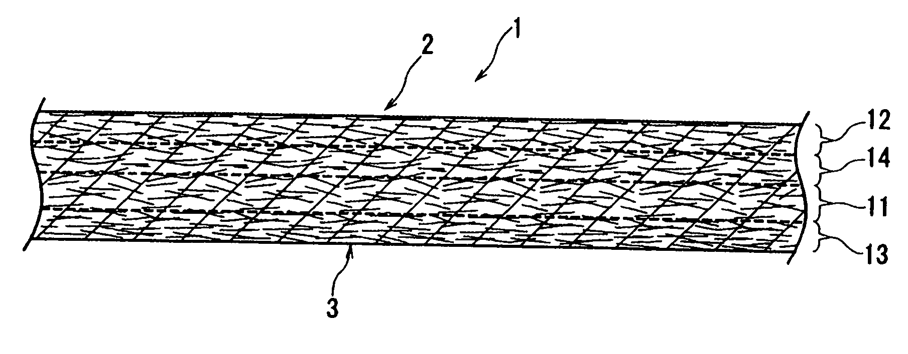
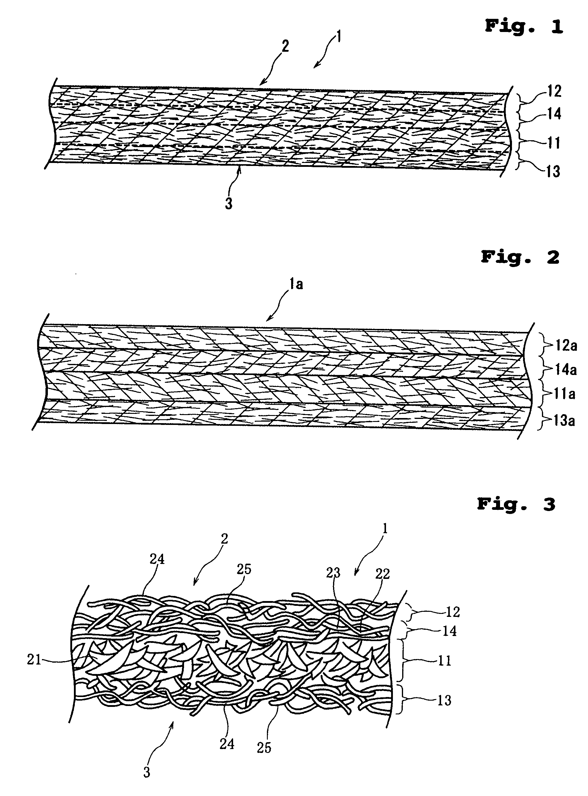
[0035]FIG. 1 is an enlarged sectional view of a wiper 1 according to the present invention; FIG. 2 is an enlarged sectional view of a multilayered fibrous web 1a prepared in the process for manufacturing the wiper 1; and FIG. 3 is an enlarged sectional view schematically showing the internal structure of the wiper 1.

[0036] First of all, fibers constituting layers of the wiper 1 will be described. Fibers as used herein are broadly divided into “fusible fiber” and “non-fusible fiber”. The term “non-fusible fiber” includes “hydrophilic fiber” and “hydrophobic fiber”. The term “hydrophilic fiber” includes “cellulosic fiber” and “synthetic resin fiber treated to be hydrophilic”. That is, the term “non-fusible fiber” refers to fiber whose surface has a higher melting point than that of the “fusible fiber” or is not allowed to melt. Meanwhile, the term “fusible fiber” includes synthetic resin fiber treated to be hydrophilic and hydrophobic fibers (hydrophobic synthetic resin fibers).

[0037...

second embodiment

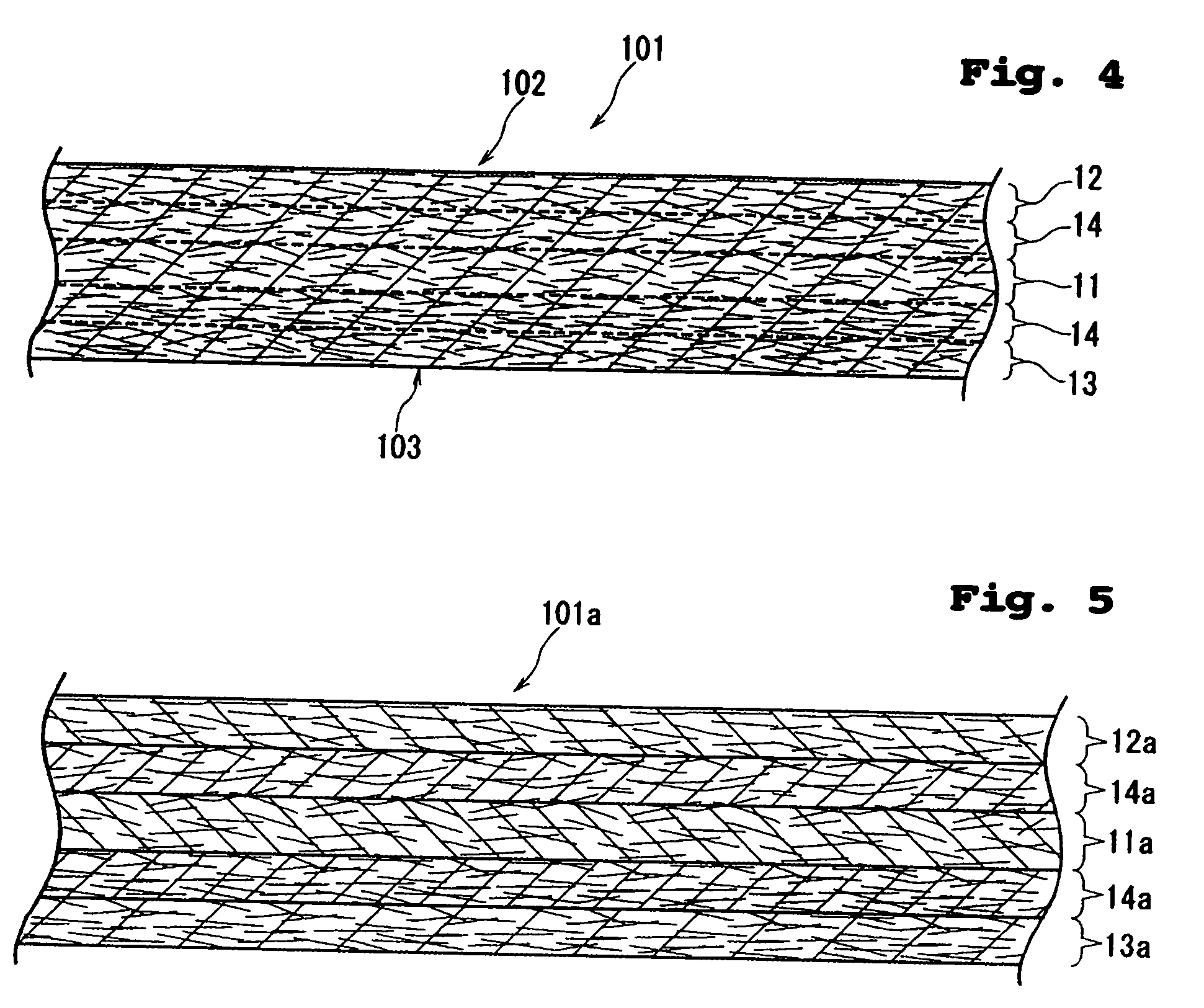
[0059]FIG. 4 is an enlarged sectional view of a wiper 101 according to the present invention, and FIG. 5 is an enlarged sectional view of a multilayered fibrous web 101a prepared in the process for manufacturing the wiper 101.

[0060] The wiper 101 of FIG. 4 includes two reinforcing layers 14, 14 on both sides of the interlining layer 11, wherein one reinforcing layer 14 is covered with the first surfacing layer 12 and the other reinforcing layer 14 is covered with the second surfacing layer 13.

[0061] As shown in FIG. 5, the multilayered fibrous web 101a is formed by stacking a second surfacing layer-forming fibrous web 13a, a reinforcing layer-forming fibrous web 14a, an interlining layer-forming fibrous web 11a, a reinforcing layer-forming fibrous web 14a and a first surfacing layer-forming fibrous web 12a one on top of the other.

[0062] The individual fibrous webs are constituted in the same manner as in the first embodiment and the wiper 1 is manufactured also in the same manner ...


PUM

PropertyMeasurementUnit
lengthaaaaaaaaaa
lengthaaaaaaaaaa
lengthaaaaaaaaaa

Abstract

Disclosed is a wiper which is which is highly retentive of water, soft to the touch, and improved in sheet strength and a method for manufacturing the same. An interlining layer contains pulp fibers, first and second surfacing layers contain non-fusible fibers, and a reinforcing layer contains fusible fibers and rayon fibers. The fusible fibers are fusion-bonded but the non-fusible fibers remain unfused. Sheet surfaces are free from the fusible fibers.

Description

BACKGROUND OF THE INVENTION [0001] 1. Field of the Invention [0002] The present invention relates to a wiper intended to be used for wiping the human body, furniture, home fixtures and so on in a pre-moistened or dry state and a method for manufacturing the same. [0003] 2. Description of the Related Art [0004] Nonwoven wipers have been widely used to wipe the human body, furniture, home fixtures and so on. Such wipers may be used in a dry state to absorb water during use or in a pre-moistened state. In either case, nonwoven wipers are formed of hydrophilic fibers such as rayon and synthetic resin fibers. [0005] Japanese Patent No. 3183818 discloses a wet tissue in which an interlining layer is disposed between upper and lower layers. The upper and lower layers contain hydrophobic fibers at a higher proportion than hydrophilic fibers whereas the interlining layer contains hydrophilic fibers at a higher proportion than hydrophobic fibers. Fibers constituting these layers are entangled...

Claims


Application Information

Patent Timeline
Patent Type & Authority Applications(United States)
IPC IPC(8): A47K7/00A47L13/16D04H13/00D06M17/00
CPCA47L13/16Y10T442/692Y10T442/659Y10T442/663Y10T442/666Y10T442/69Y10T442/667Y10T442/662D04H1/485D04H1/498D04H1/541Y10T428/24992D04H1/5412D04H1/5414D04H1/5418B42D5/04B42P2241/10
Inventor BANDO, TAKESHIMIYAKE, DAISUKETOMITA, KATSUSHIISHIKAWA, HIDEYUKI
Owner UNI CHARM CORP
Learn More