Centrifugal compressor for heavy oil hydrogenation device

A centrifugal compressor, heavy oil hydrogenation technology, applied in the components of pumping devices for elastic fluids, mechanical equipment, machines/engines, etc., can solve problems such as no reference value and technical inspiration, and reduce axial Thrust, smooth running effect

Inactive Publication Date: 2018-03-23
SHENYANG SITE MACHINERY MFG
View PDF6 Cites 1 Cited by
  • Summary
  • Abstract
  • Description
  • Claims
  • Application Information

AI Technical Summary

Problems solved by technology

It also has no reference value and technical inspiration for us

Method used


Image

  • Centrifugal compressor for heavy oil hydrogenation device
  • Centrifugal compressor for heavy oil hydrogenation device
  • Centrifugal compressor for heavy oil hydrogenation device

Examples


Embodiment 1

[0027] Example 1 Circulating hydrogen compressor for residual oil hydro-upgrading unit

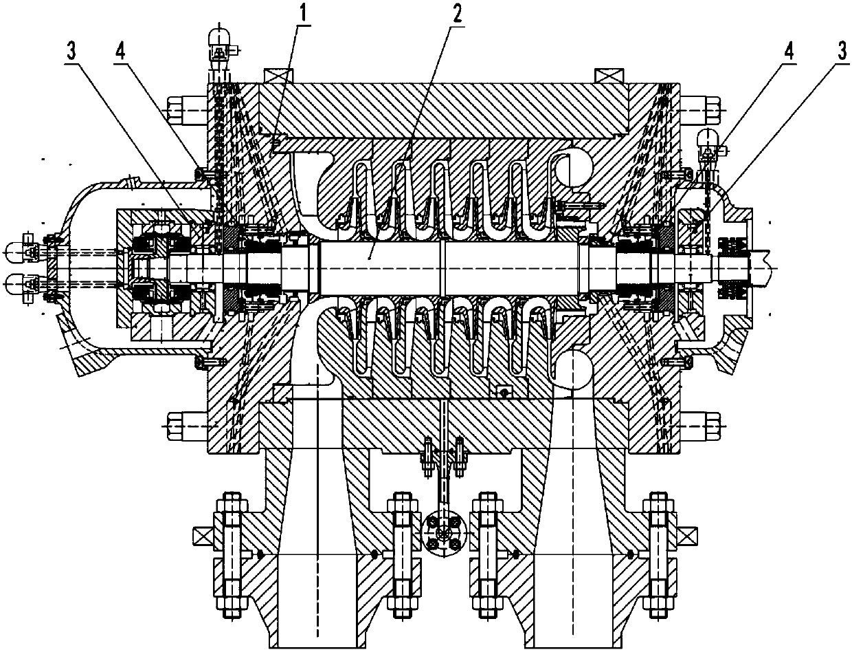
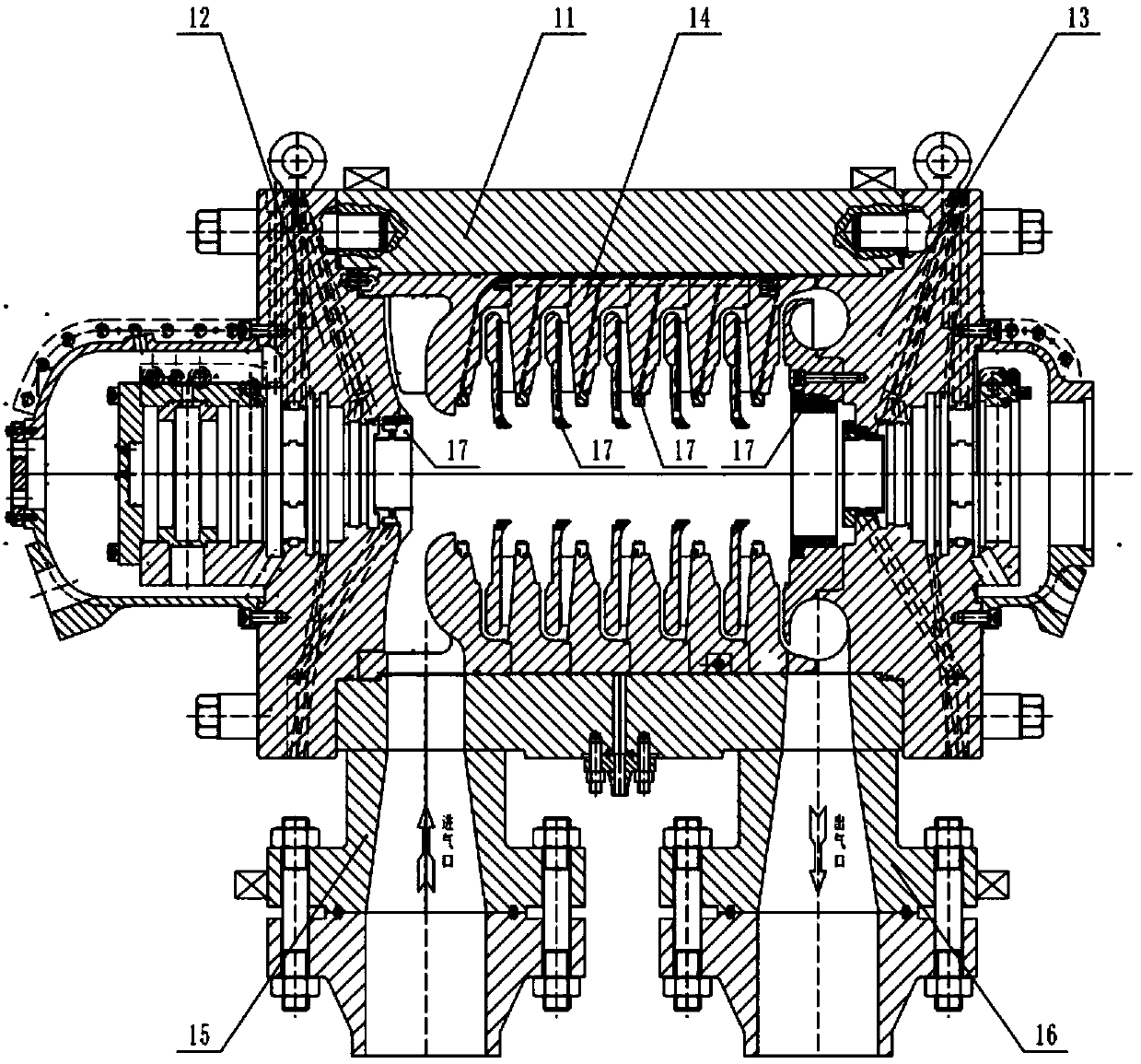
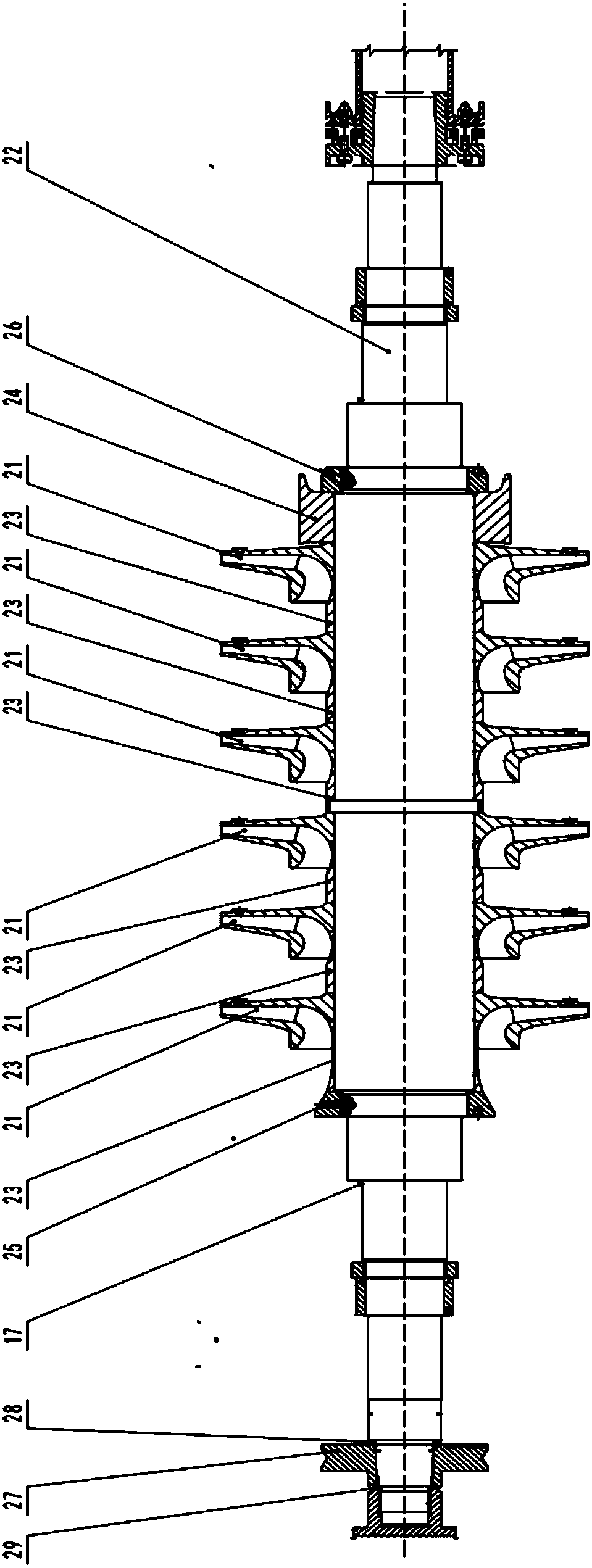
[0028] This embodiment 1 is a circulating hydrogen compressor for a residual oil hydrogenation upgrading device, which is a kind of heavy oil hydrogenation device, and this set of devices can effectively utilize the remaining substances after purifying light oil in petrochemical plants , After hydrotreating, heavy oil can be converted into light oil and middle distillate, forming a relatively clean energy source. The structure of the circulating hydrogen compressor used in residual oil hydrogenation is a vertical split structure, and the general operating pressure can reach 15-20Mpa, and the pressure of some devices can exceed 20Mpa. Six-stage centrifugal compressor, the impeller adopts a binary closed impeller, and its blade adopts a backward curved structure; the diffuser adopts a vaneless diffuser.

Embodiment 2

[0029] Example 2 Circulating hydrogen compressor for wax oil hydro-upgrading unit

[0030] This embodiment 2 is a circulating hydrogen compressor for a wax oil hydrotreating and upgrading unit, which is also a kind of heavy oil hydrogenation unit. This set of equipment can effectively utilize the remaining oil after purifying light oil in petrochemical plants After hydrotreating, heavy oil can be converted into light oil and middle distillate, forming a cleaner energy source. The structure of the circulating hydrogen compressor used in the hydrogenation of wax oil is a vertical split structure, and the general operating pressure can reach 15-20Mpa. Eight-stage centrifugal compressor, the impeller adopts a closed impeller, the impeller adopts a binary structure, and its blades adopt a backward curved structure, and the blades of the front and rear impellers are deflected by 15 degrees; a bladeless diffuser is used.

Embodiment 3

[0031] Embodiment 3 Circulating hydrogen compressor for naphtha hydro-upgrading unit

[0032] Example 3 is a circulating hydrogen compressor for a naphtha hydro-upgrading device, which is also a kind of heavy oil hydrogenation device. This device can effectively utilize the naphtha produced by a petrochemical plant, and undergo hydrogenation treatment It can convert naphtha into light oil and middle distillate to form a relatively clean energy source. The structure of the circulating hydrogen compressor used in naphtha hydrogenation is a vertical split structure, and the general operating pressure is less than 10Mpa, and the pressure will vary depending on the process. The corresponding parameters will also change. The number of impellers varies from 6 to 8, and the diameter of the impeller varies from 400mm to 800mm. The impeller still adopts a binary closed impeller, and its blades adopt a backward curved structure; The compressor uses a vaneless diffuser.

[0033] The abo...


PUM


Abstract

A centrifugal compressor for a heavy oil hydrogenation device is composed of the four parts of a stator assembly, a rotor assembly, a bearing group and dry gas seals. The stator assembly comprises a cylinder block, end covers, partition plates and a seal. The rotor assembly comprises 6-8 impellers, a main shaft, spacer sleeves, a balance disk, a thrust disk, nuts, an adjusting pad and a stopper ring. The bearing group comprises two supporting bearings and a thrust bearing. The dry gas seals are provided with independent control units and independent systems and each comprises a body and a control portion. The centrifugal compressor for the heavy oil hydrogenation device is characterized in that (1) the compressor is of a vertical subdivision type structure; (2) the partition plates are assembled together to form a partition plate bundle, and a bladeless diffuser is arranged between every two adjacent partition plates; (3) the 6-8 impellers are sequentially arranged on the main shaft, and the diameter of each impeller is 400 mm; (4) the blade forms of the impellers are identical, and the blades of one impeller deviate by a certain angle relative to the blades of the impeller locatedin the front; (5) the supporting bearings are titling-pad bearings, the thrust bearing is of the Kingsbury type, and the two sides of the thrust bearing are of the same structure; (6) the dry gas seals are installed at the two ends of the compressor, and the dry gas seals are provided with the independent control systems.

Description

technical field [0001] The invention belongs to the technical field of petrochemical industry, and in particular relates to a centrifugal compressor used for supporting a heavy oil hydrogenation device. Background technique [0002] The earliest heavy oil (residual oil) hydrogenation process technology began in the 1950s, using distillate oil containing sulfur or high sulfur crude oil for hydrodesulfurization, and the desulfurized vacuum distillate oil was then mixed with vacuum heavy oil to produce sulfur content More than 1% of fuel oil, so this process is also called indirect desulfurization process. [0003] Heavy oil hydrogenation has two purposes: (1) Heavy oil hydrodesulfurization to produce low-sulfur fuel oil. Obtain low-sulfur fuel oil to solve environmental pollution problems. (2) Hydrogenation of heavy oil makes the oil lighter, and a part of light oil and middle distillate can be obtained. [0004] What the heavy oil hydro-upgrading process requires is a sp...

Claims


Application Information

Patent Timeline
Patent Type & Authority Applications(China)
IPC IPC(8): F04D17/12F04D29/44F04D29/28F04D29/30F04D29/056F04D29/10
CPCF04D17/125F04D29/056F04D29/102F04D29/286F04D29/30F04D29/441
Inventor 石雪松
Owner SHENYANG SITE MACHINERY MFG
Why Eureka
Try Eureka