
Automatic cleaning device for internal components of combing machine

A technology for automatic cleaning and internal parts, used in combers, fiber processing, textiles and papermaking, etc., can solve the problems of inability to meet the cleaning process, poor cleaning effect, etc., to avoid falling and drifting.

Active Publication Date: 2019-09-13
江苏展东纺织机械专件有限公司
View PDF15 Cites 2 Cited by
  • Summary
  • Abstract
  • Description
  • Claims
  • Application Information

AI Technical Summary

Problems solved by technology

[0003] Publication No. CN101285222B provides a combing machine brush roller automatic cleaning device and its cleaning method. This device drives the combing machine brush roller and the lead screw to rotate forward through the motor, and the lead screw drives the reciprocating mobile trolley to move on the lead screw , so that the brush roller of the combing machine is rotated forward and reverse repeatedly, and the reciprocating moving trolley then reciprocates on the surface of the brush roller of the combing machine to move left and right to clean out the sundries adhered to the comb needles on the surface of the brush roller of the combing machine. Induced fan suction, this device will eventually suck away the lint or impurities through the fan during the cleaning process, and will suck out the debris along the brush roller during the negative air pressure process of the fan, and at this time part of the debris will be On the re-adhesive brush roll, the cleaning effect is not good, and it has been disclosed in the prior art that more than the brush roll will stick to the sundries in the combing machine, and this device only uses the cleaning of the brush roll. meet the cleaning process

Method used


Image

  • Automatic cleaning device for internal components of combing machine
  • Automatic cleaning device for internal components of combing machine
  • Automatic cleaning device for internal components of combing machine

Examples


Embodiment

[0025] see Figure 2 to Figure 6 , the present invention provides a technical solution:

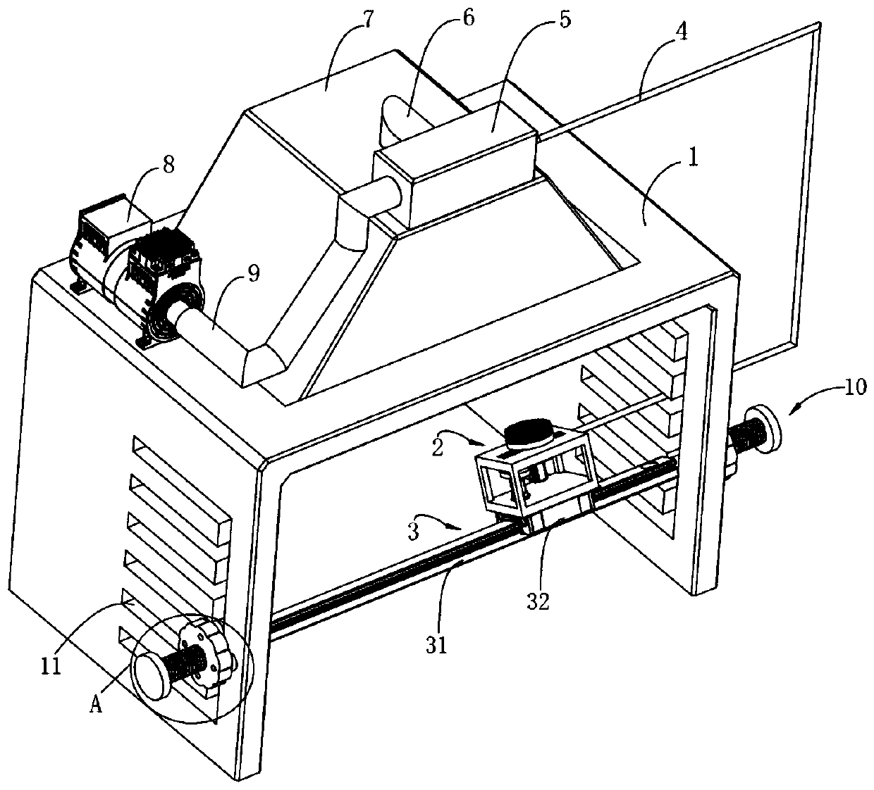
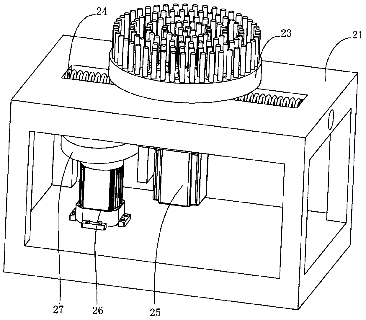
[0026] An automatic cleaning device for the internal parts of a combing machine, including a frame 1, a cleaning mechanism 2, a linear drive mechanism 3, a telescopic hose 4, a bag filter 5, an air outlet pipe 6, a dust cover 7, a fan 8, and an air inlet Trachea 9 and regulating mechanism 10, wherein:

[0027] The two sides of the frame 1 are provided with interconnected guide grooves 11, wherein the guide grooves 11 are set in both horizontal and vertical directions, the dust collection cover 7 is fixedly installed above the frame 1, and the bag dust collector 5 is installed on the dust collector. On the cover 7, it communicates with the dust collection cover 7 through the air outlet pipe 6, wherein the bag filter 5 is used for filtering impurities, and the fan 8 is fixed on the frame 1 through bolts, and it is connected to the bag filter 5 through the air inlet pipe 9. connected;

[...


PUM


Abstract

The invention provides an automatic cleaning device for internal components of a combing machine. A linear drive mechanism is arranged at guide grooves in a rack, a support frame in the cleaning mechanism is mounted on the linear drive mechanism, a slide block is movably mounted on the support frame, a cleaning brush is rotationally mounted on the slide block, the interior of the cleaning brush isof a cavity structure, and a through hole is formed in the position where the cleaning brush is in contact with the slide block; one end of a telescopic hose is in seal connection with a bag dust collector, and the other end is mounted on an air inlet hole in the slide block in a sealed manner; two adjusting mechanisms are located on the linear drive mechanism respectively. Cotton wool on rollerscan be cleaned more effectively by rotation and reciprocating motion of the cleaning brush, the left and right are communicated by the telescopic hose, and the cotton wool can be directly adsorbed and discharged during cleaning of the cotton wool by the cleaning brush, and can be prevented from falling and wafting accordingly; a linear guide rail can move vertically and bilaterally on the guide groove by pulling a mounting disc, so that the rollers in different positions can be cleaned.

Description

technical field [0001] The invention relates to the technical field of textile equipment, in particular to an automatic cleaning device for internal parts of a combing machine. Background technique [0002] Existing straight cotton combing machines such as figure 1 As shown, the cotton material passes through the cotton reel 1, the unwinding roller 2, the cotton feeding roller 3, the upper nipper 4, the lower nipper 5, the cylinder 6, the top comb 7, the extraction and separation mechanism 8, the pulling stretching mechanism 9, rear bell mouth 10, and pressure roller 11, and a front bell mouth 17 is also provided between the extracting and separating mechanism 8 and the drafting mechanism 9 to bundle the cotton layer into noodles, and turn to 90 degrees horizontally by turning nails 18. °, the dotted line part in the figure is a schematic diagram, the actual position of the dotted line part is obtained from the side view, and the actual direction of the sliver in the dotted...

Claims


Application Information

Patent Timeline
IPC IPC(8): D01G19/22D01G19/26
CPCD01G19/22D01G19/26
Inventor 郭三灯
Owner 江苏展东纺织机械专件有限公司
Learn More