Calculus gripping device for urinary surgery

A urology and grasping device technology, applied in the medical field, can solve the problems that broken stones cannot be discharged with the cleaning solution, the cleaning effect is not thorough enough, and the efficiency of stone extraction is reduced, so as to avoid difficult handling, prevent bladder infection, and facilitate operation Effect

Pending Publication Date: 2022-06-07
HENAN CANCER HOSPITAL
View PDF0 Cites 0 Cited by
  • Summary
  • Abstract
  • Description
  • Claims
  • Application Information

AI Technical Summary

Problems solved by technology

[0007] In view of the above situation, in order to overcome the defects of the prior art, the present invention provides a stone grabbing device for urology, which effectively solves the problem that the stones often fall off and remain in the In the patient's body, the problem of reducing the efficiency of stone extraction and the structure of the existing flushing device is relatively simple. During flushing, more cleaning fluid needs to be poured into the patient's bladder, and the cleaning effect is poor, and larger particles of gravel cannot be discharged with the cleaning fluid. , the cleaning effect is not thorough enough

Method used


Image

  • Calculus gripping device for urinary surgery
  • Calculus gripping device for urinary surgery
  • Calculus gripping device for urinary surgery

Examples


Embodiment 1

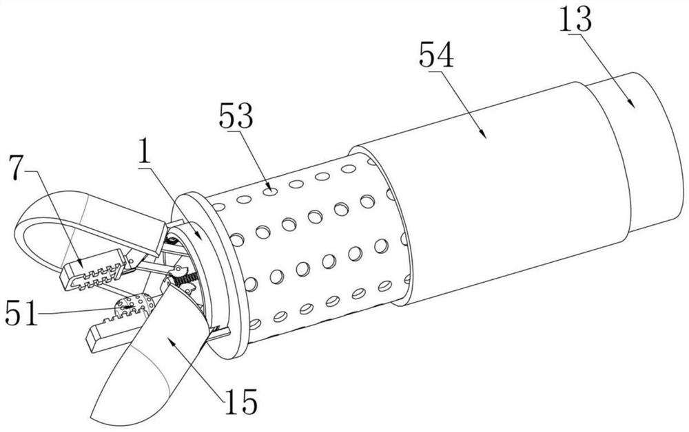
[0040] Example one, as Figure 1-15As shown, a urology calculus grasping device includes an insertion tube 1, and a delivery screw 2 is rotatably installed in the insertion tube 1, and the delivery screw 2 is threadedly mounted on the insertion tube 1 and slid left and right. The conveying plate 3 on the upper side, the conveying plate 3 can only slide left and right in the insertion tube 1, and will not rotate. The front and rear ends of the front side are respectively rotated and installed with a left push rod 5, and there is a certain distance between the right push rod 4 and the left push rod 5 on the same side. A connecting rod 6 is rotated and installed between them, and a clamping block 7 is fixedly installed on the left end of each connecting rod 6. The two clamping blocks 7 are respectively provided with bearing bins 8 on the end faces close to each other. The said clamping block 7 is respectively fixedly installed with a friction block 9 located around the bearing b...

Embodiment 2

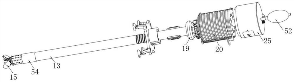
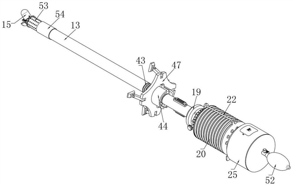
[0043] Embodiment 2, on the basis of Embodiment 1, as figure 2 , 3 , 12 and 14, a cleaning tube 13 is coaxially fixed and sleeved on the insertion tube 1. The left end of the cleaning tube 13 and the insertion tube 1 are in a closed structure, and the insertion tube 1 and the cleaning tube 13 are closed. A liquid inlet silo 14 is formed therebetween, and the front and rear ends of the left side of the insertion tube 1 are respectively rotatably installed with clamping shells 15. Each of the clamping shells 15 has a semicircular structure, and the interior is a cavity structure. A driving gear 16 is coaxially and fixedly installed on the rotating shaft of the gripping shell 14, and a power rod 17 located in the liquid inlet silo 14 is slidably installed on the front and rear ends of the cleaning pipe 13. Each power rod The left ends of 17 are respectively fixedly installed with driving racks 18 meshing with the driving gears 16 on the same side;

[0044] When encountering re...

Embodiment 3

[0045] Embodiment 3, on the basis of embodiment 2, as Image 6 , 13 As shown in , 14 and 15, the inserting tube 1 is coaxially and fixedly installed with a mixing ring 19 that communicates with the liquid inlet silo 14. The interior of the mixing ring 19 is a cavity structure, and the right end of the cleaning tube 13 is fixedly connected to On the left end surface of the mixing ring 19 , the cleaning pipe 13 communicates with the mixing ring 19 during use. The insertion pipe 1 is fixedly installed with a threaded pressing pipe 20 located on the right side of the mixing ring 19 . When the threaded pressing pipe 20 is pressed When the pressure is applied, the threaded pressing tube 20 is compressed at this time. When the pressure is no longer applied to the threaded pressing tube 20, it can be automatically restored to the original state. The mixing ring 19 and the threaded pressing tube 20 are connected by a switching device. Limiting plates 21 are respectively fixedly instal...


PUM


Abstract

The invention provides a calculus gripping device for urinary surgery, and effectively solves the problems that calculus often slides off and is left in the body of a patient due to insufficient friction force when the calculus is clamped by tweezers or operating forceps, and the calculus removing efficiency is reduced. The problems that a large amount of cleaning liquid needs to be injected into the bladder of a patient during flushing, the cleaning effect is poor, large-particle broken stones cannot be discharged along with the cleaning liquid, and the cleaning effect is not thorough enough are solved. A conveying screw rod is rotatably mounted in the inserting pipe, a conveying plate slidably mounted on the inserting pipe is mounted on the conveying screw rod in a threaded mode, right pushing rods are rotatably mounted at the front end and the rear end of the right side of the conveying plate correspondingly, and left pushing rods are rotatably mounted at the front end and the rear end of the front side of the conveying plate correspondingly; and through cooperation of a power rod, a driving rack, a driving gear and a clamping shell, large-particle stones can be treated more conveniently, and the situation that the large-particle stones are difficult to treat, and pain is brought to a patient is avoided.

Description

technical field [0001] The invention relates to the field of medical technology, in particular to a calculus grasping device for urology. Background technique [0002] Bladder stones are stones that form in the bladder, and are divided into primary bladder stones and secondary bladder stones. The former refers to the formation of stones in the bladder, mostly caused by malnutrition, mostly in children. With the continuous development of my country's economy, children's bladder stones are now showing a downward trend. The latter refers to bladder stones originating from upper urinary tract or secondary to lower urinary tract obstruction, infection, bladder foreign body or neurogenic bladder. In economically developed areas, bladder stones mainly occur in elderly men, and most of them suffer from benign prostatic hyperplasia or urethral stricture. In addition to malnutrition factors, lower urinary tract obstruction, infection, bladder foreign body, and metabolic diseases can...

Claims


Application Information

Patent Timeline
Patent Type & Authority Applications(China)
IPC IPC(8): A61B17/22
CPCA61B17/22031A61B2217/005A61B2217/007A61B2017/22034A61B2017/22035A61B2017/22038A61B2017/22079A61B2017/22082
Inventor 田沛任君凯白吉彦
Owner HENAN CANCER HOSPITAL
Why Eureka
Try Eureka