Power distribution cabinet assembling machine

A power distribution cabinet group and electric power technology, applied in metal processing, metal processing equipment, manufacturing tools, etc., can solve the problems of high labor intensity, long time consumption, cumbersome and complicated process, etc., to reduce labor intensity and improve work efficiency , the effect of simple operation

Active Publication Date: 2018-09-28
东营胜华科贸有限公司
View PDF6 Cites 2 Cited by
  • Summary
  • Abstract
  • Description
  • Claims
  • Application Information

AI Technical Summary

Problems solved by technology

[0003] In order to solve the above problems, the present invention provides a power distribution cabinet assembly machine, which can solve the problem that when installing screws in the power distribution cabinet, it needs to be tightened with a corresponding screwdriver. The process is cumbersome and complicated. At the working hole, the personnel use tools to tighten and install the screws. Due to the small size of the screws, the screws may fall during manual installation. When installing different specifications of hexagonal screws, personnel need to use corresponding tools to work. It is inconvenient for personnel to carry, the process takes a long time, the labor intensity is high, and the efficiency is low. It can realize the function of targeted positioning of the outer hexagonal screws of different specifications, and the targeted positioning of the outer hexagonal screws of different specifications. Manual installation, no screw falling, short time-consuming, and has the advantages of simple operation, low labor intensity and high work efficiency

Method used


Image

  • Power distribution cabinet assembling machine
  • Power distribution cabinet assembling machine
  • Power distribution cabinet assembling machine

Examples


Embodiment Construction

[0022] In order to make the technical means, creative features, goals and effects achieved by the present invention easy to understand, the present invention will be further described below in conjunction with specific illustrations. It should be noted that, in the case of no conflict, the embodiments in the present application and the features in the embodiments can be combined with each other.

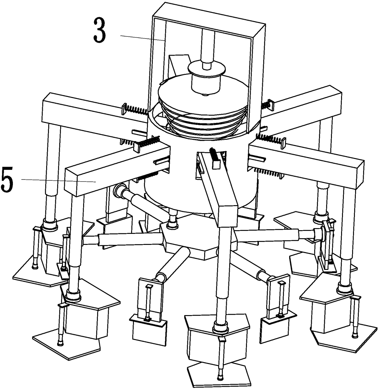
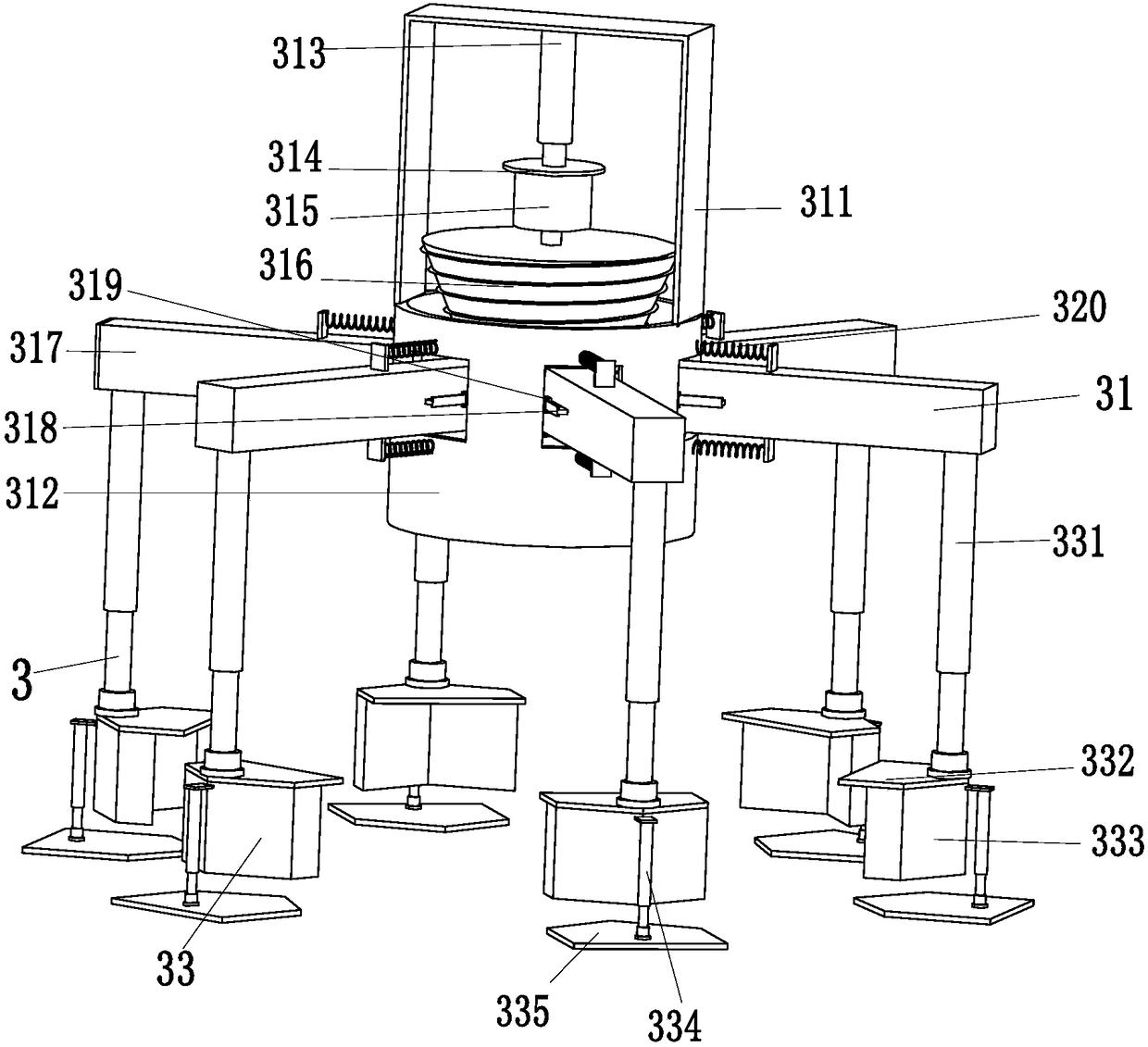
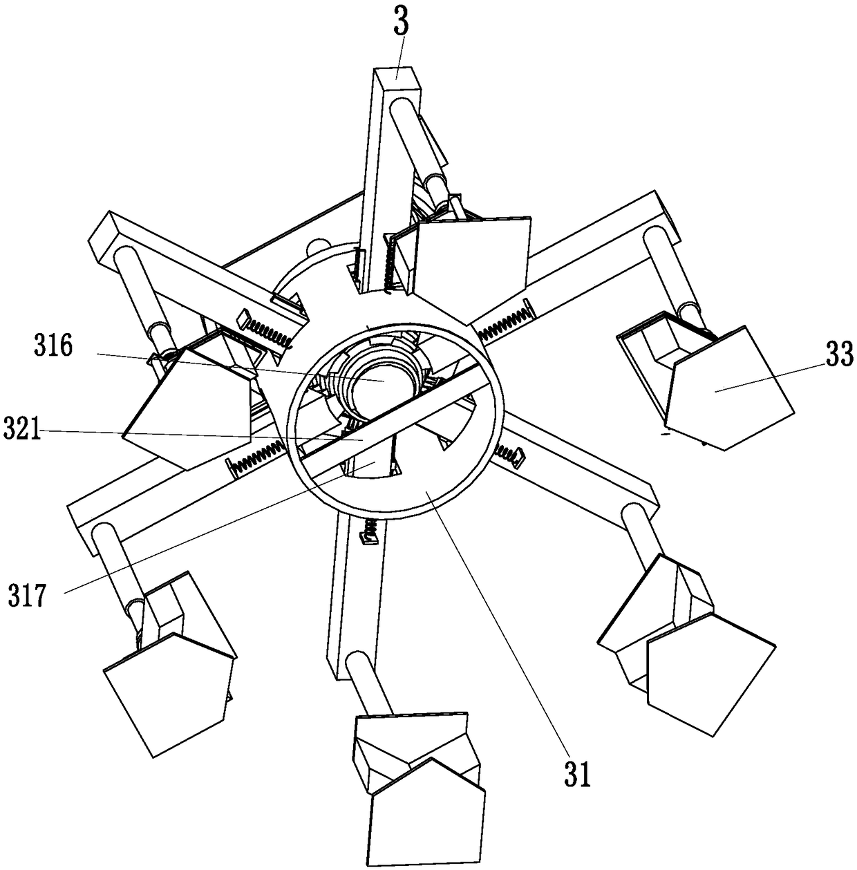
[0023] Such as Figure 1 to Figure 4 As shown, in order to achieve the above purpose, the present invention adopts the following technical solutions: a power distribution cabinet assembly machine, including an adjustment device 3 and a dual-purpose limit device 5, and the lower end of the adjustment device 3 is installed with a dual-purpose limit device 5.

[0024] The adjusting device 3 includes a radius adjusting mechanism 31 and six outer corner limiting mechanisms 33, and the middle part of the radius adjusting mechanism 31 is evenly equipped with six outer corner limiting mecha...


PUM


Abstract

The invention relates to a power distribution cabinet assembling machine which comprises an adjusting device and a dual-purpose limiting device, wherein the dual-purpose limiting device is mounted atthe lower end of the adjusting device. The power distribution cabinet assembling machine provided by the invention can solve the problems that when screws are mounted on the power distribution cabinetat present, the screws need to be screwed up with corresponding screw drivers, the screws are commonly placed in work holes if being mounted, personnel screws up and mount the screws by means of tools then, as the screws are small, the screws may fall if being mounted manually, and when hex screws of different specifications are mounted, personnel works by means of corresponding tools, the consumed time in the process is long, the labor intensity is great and the efficiency is low and the like. The power distribution cabinet assembling machine can achieve a function of limiting the hex screwsof different specifications in a targeted manner without mounting the screws manually, so that the condition that the screws fall is avoided, the consumed time is short, and the power distribution cabinet assembling machine has the advantages of being simple to operate, small in labor intensity, high in work efficiency and the like.

Description

technical field [0001] The invention relates to the field of installation of power distribution cabinets, in particular to an assembly machine for power distribution cabinets. Background technique [0002] The power distribution cabinet (box) is divided into power distribution cabinet (box), lighting distribution cabinet (box), metering cabinet (box), and is the final equipment of the power distribution system. The cabinet is used in the occasions where the load is relatively scattered and there are few circuits. The motor control center is used in the occasions where the load is concentrated and there are many circuits. They distribute the electric energy of a certain circuit of the upper-level power distribution equipment to the nearby load. The load provides protection, monitoring and control. The structure of the distribution box is divided into two types, one is a welded structure, and the other is an assembled structure. The assembled structure processes the sheet meta...

Claims


Application Information

Patent Timeline
Patent Type & Authority Applications(China)
IPC IPC(8): B23P19/06
CPCB23P19/06
Inventor 王柏彰
Owner 东营胜华科贸有限公司
Why Eureka
Try Eureka