Internal and external fault recognition method utilizing transient energy

A technology of transient energy and fault identification, applied in fault location, fault detection by conductor type, information technology support system, etc., can solve problems such as inability to identify faults inside and outside the area, achieve obvious differences, simple overall logic structure, and algorithm. simple effect

Inactive Publication Date: 2019-09-13
KUNMING UNIV OF SCI & TECH
View PDF6 Cites 4 Cited by
  • Summary
  • Abstract
  • Description
  • Claims
  • Application Information

AI Technical Summary

Problems solved by technology

In a traditional DC system, a parallel filter and a series DC reactor are connected at the outlet of the converter station to perform filtering and current limiting functions. The difference of boundary characteristics can reliably identi

Method used


Image

  • Internal and external fault recognition method utilizing transient energy
  • Internal and external fault recognition method utilizing transient energy
  • Internal and external fault recognition method utilizing transient energy

Examples


Embodiment 1

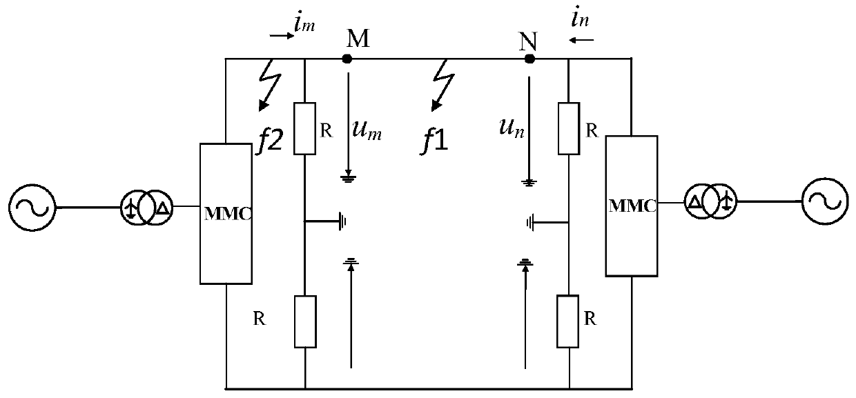
[0056] Example 1: The simulation model of a 300kV modular multilevel converter DC transmission line is as follows figure 1 shown. Its line parameters are as follows: The total length of the direct current transmission line is 400km. Fault location: The positive line is 100km away from the M terminal. The sampling frequency is 10kHz.

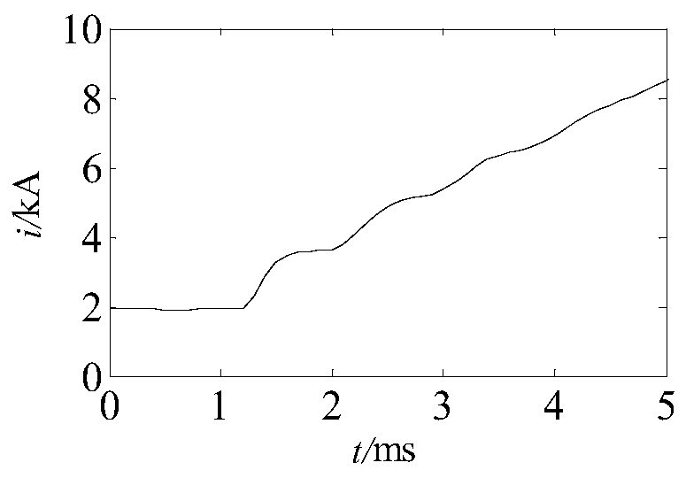
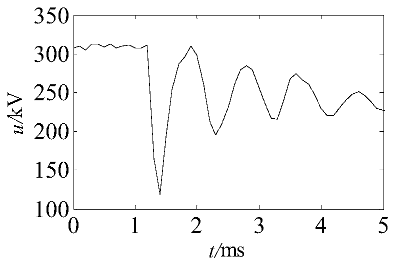
[0057] (1) Obtain the waveform and data of the measured terminal voltage and current according to the first step in the manual. The waveform is as follows figure 2 , image 3 , Figure 4 and Figure 5 shown.

[0058] (2) According to the second step in the manual, the waveform and data of the voltage and current fault components on both sides can be obtained, and the waveform is as follows Figure 6 , Figure 7 , Figure 8 and Figure 9 shown.

[0059] (3) Obtain the transient energy E on both sides according to the transient energy calculation formula in the third step of the manual M and E N ,As shown in Table 1.

[0060] (4) Acc...

Embodiment 2

[0063] Example 2: The simulation model of a 300kV modular multilevel converter DC transmission line is as follows figure 1 shown. Its line parameters are as follows: The total length of the direct current transmission line is 400km. Fault location: The positive pole at the DC outlet of the rectifier side is faulty. The sampling frequency is 10kHz.

[0064] (1) Obtain the waveform and data of the measured terminal voltage and current according to the first step in the manual. The waveform is as follows Figure 10 , Figure 11 , Figure 12 and Figure 13 shown.

[0065] (2) According to the second step in the manual, the waveform and data of the voltage and current fault components on both sides can be obtained, and the waveform is as follows Figure 14 , Figure 15 , Figure 16 and Figure 17 shown.

[0066] (3) Obtain the transient energy E on both sides according to the transient energy calculation formula in the third step of the manual M and E N ,As shown in ta...


PUM

PropertyMeasurementUnit
Full lengthaaaaaaaaaa

Abstract

The invention relates to an internal and external fault recognition method utilizing transient energy and belongs to the technical field of high-voltage direct current transmission line fault recognition of modular multilevel converters. Firstly, voltage and current of a measurement end of a positive pole line acquired by a measurement end high-speed acquisition device are read; secondly, voltageand current fault components in a 5 ms time window are obtained according to the acquired voltage and current and the voltage and the current in a steady state; the obtained fault components are multiplied and integrated so as to obtain the transient energy, afterwards, the positive and negative of the transient energy product of the lines on the two sides are judged, if the transient energy product is positive, the fault is an internal fault, and if the transient energy product is negative, the fault is an external fault. According to the method in the invention, the transient energy in the short-time window after the fault is calculated, the difference between the line fault and the external fault is obvious, and reliable pole selection is facilitated. The algorithm of obtaining the transient energy is simple, and the integral logic structure is simple.

Description

technical field [0001] The invention relates to an internal and external fault identification method using transient energy, and belongs to the technical field of high-voltage direct current transmission line fault identification of modular multilevel converters. Background technique [0002] Modular multilevel converters are widely used in flexible direct current transmission systems due to factors such as low manufacturing difficulty, strong scalability, low loss, and strong fault handling. Compared with the traditional DC system, the overcurrent capability of the fully-controlled power electronic devices is poor, and the high-voltage DC transmission system of the modular multilevel converter is poor in the ability to withstand the impact of faults, so it can quickly identify faults inside and outside the fault area, and respond accordingly Protective action is particularly important. In a traditional DC system, a parallel filter and a series DC reactor are connected at t...

Claims


Application Information

Patent Timeline
IPC IPC(8): G01R31/08
CPCG01R31/086Y04S10/52
Inventor 束洪春张雪飞田鑫萃代月梁雨婷
Owner KUNMING UNIV OF SCI & TECH
Why Eureka
Try Eureka