Channel visualization device

A channel and installation groove technology, which is applied in the field of channel visualization devices, can solve the problems of lens contamination of the visualization device, and achieve the effect of improving the visibility of the field of view and improving the cleanliness.

Inactive Publication Date: 2019-09-13
GUANGZHOU POWER SUPPLY BUREAU GUANGDONG POWER GRID CO LTD
View PDF13 Cites 7 Cited by
  • Summary
  • Abstract
  • Description
  • Claims
  • Application Information

AI Technical Summary

Problems solved by technology

[0004] Based on this, it is necessary to provide a channel visualization device for how to avoid the lens pollution problem of the visualization device

Method used


Image

  • Channel visualization device
  • Channel visualization device
  • Channel visualization device

Examples


Embodiment Construction

[0024] In order to make the above objects, features and advantages of the present invention more comprehensible, specific implementations of the present invention will be described in detail below in conjunction with the accompanying drawings. In the following description, numerous specific details are set forth in order to provide a thorough understanding of the present invention. However, the present invention can be implemented in many other ways different from those described here, and those skilled in the art can make similar improvements without departing from the connotation of the present invention, so the present invention is not limited by the specific implementations disclosed below.

[0025] It should be noted that when an element is referred to as being “fixed” to another element, it can be directly on the other element or there can also be an intervening element. When an element is referred to as being "connected to" another element, it can be directly connected ...


PUM


Abstract

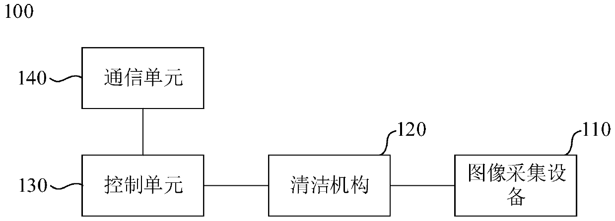
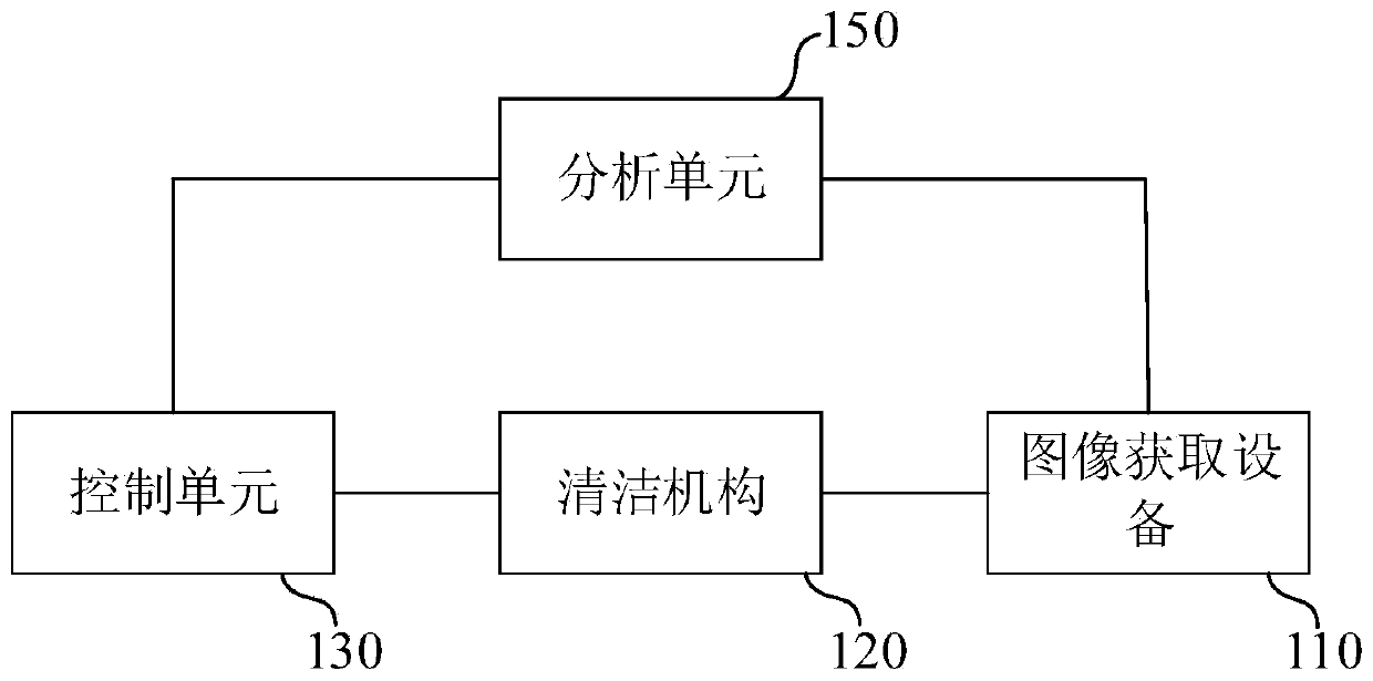
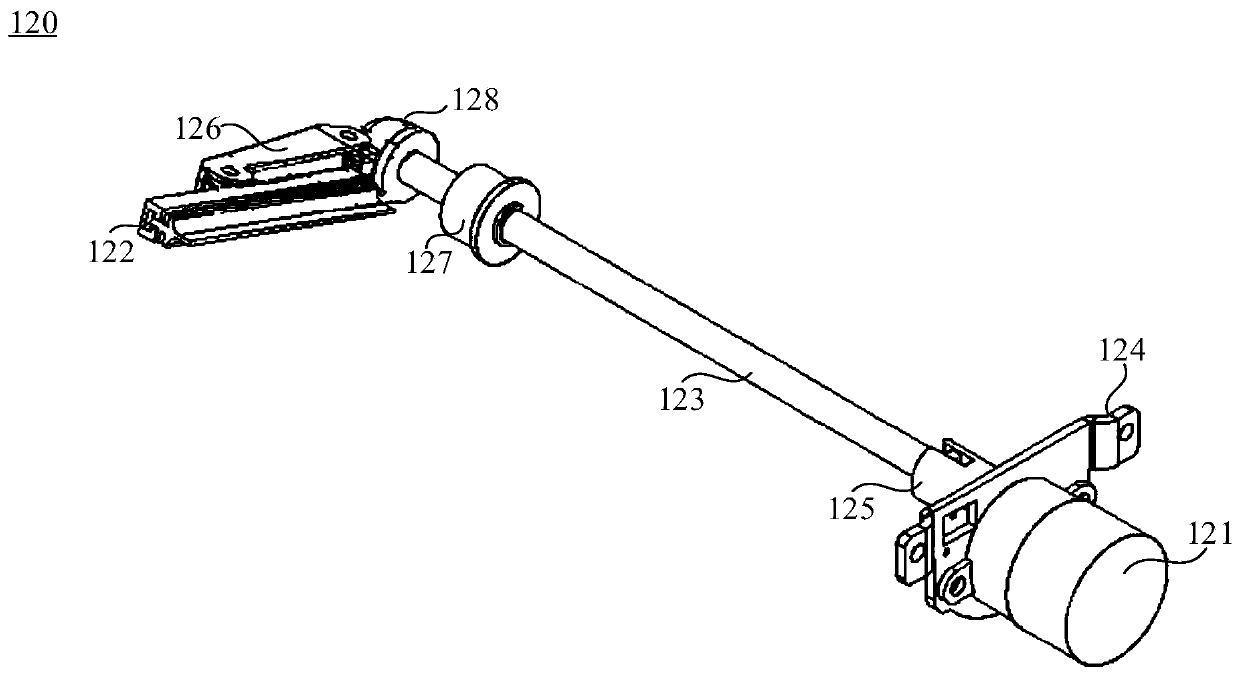
The invention relates to a channel visualization device. The channel visualization device comprises an image acquisition device and a cleaning mechanism. The image acquisition device comprises a camera, the camera is provided with a lens separation blade, and a hydrophobic coating is attached to the lens separation blade. And the cleaning mechanism is connected with the image acquisition equipment, the cleaning mechanism comprises a driving piece and a brush head in driving connection with the driving piece, and the brush head abuts against the lens separation blade. According to the channel visualization device, the lens separation blade has good hydrophobicity through the hydrophobic coating. Rainwater or fog is prevented from gathering on the surface of the lens separation blade for a long time. Meanwhile, rain, fog and dirt on the lens blocking piece are removed in time through the cleaning mechanism, the cleanliness of the lens blocking piece is improved, it is guaranteed that theimage collecting device can obtain clear images in severe weather or a dirty environment, and therefore the channel visualization device can better play the advantages of remote patrolling in the severe weather and the severe environment.

Description

technical field [0001] The invention relates to the technical field of remote video monitoring, in particular to a channel visualization device. Background technique [0002] With the development of urbanization and the growth of power supply demand, the laying range of transmission lines is becoming wider and wider. Many transmission lines are often erected in remote outdoor areas, resulting in low efficiency and time-consuming manual on-site inspections. With the development of intelligent technology and remote inspection technology, more and more visualization devices are applied to remote inspection of transmission lines. The visualization device has played an active role in timely discovering potential safety hazards of transmission lines and reducing the pressure of manual inspections. [0003] However, after long-term use of the visualization device on site, especially in bad weather such as rain and fog, the lens of the visualization device is easily blocked by ext...

Claims


Application Information

Patent Timeline
Patent Type & Authority Applications(China)
IPC IPC(8): H04N5/225H04N5/217H04N7/18B08B1/00
CPCH04N7/18B08B1/008B08B1/002H04N23/81H04N23/00
Inventor 徐涛祁宏昌张滔
Owner GUANGZHOU POWER SUPPLY BUREAU GUANGDONG POWER GRID CO LTD
Why Eureka
Try Eureka