LED constant-current driving device and driving method

A technology of constant current drive and drive method, which is applied in the direction of lighting devices, light sources, electrical components, etc., can solve the problems of poor performance and high failure rate of constant current drive circuits, and achieve no color shift, long life, and good energy-saving effect Effect

Inactive Publication Date: 2019-09-13
NINGBO UNIVERSITY OF TECHNOLOGY
View PDF4 Cites 5 Cited by
  • Summary
  • Abstract
  • Description
  • Claims
  • Application Information

AI Technical Summary

Problems solved by technology

Although the luminous efficiency of LED is gradually improving, the performance of the constant current drive circuit matching the LED lamp is not good, and the failure rate is high, which has become a bottleneck for the promotion and application of LED.

Method used


Image

  • LED constant-current driving device and driving method
  • LED constant-current driving device and driving method
  • LED constant-current driving device and driving method

Examples


Embodiment 1

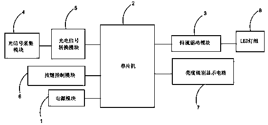
[0046] Such as figure 1 As shown, an LED constant current driving device is used to control the display of LED lamp group 8 (consisting of multiple LED lamps connected in series / parallel / series-parallel), including:

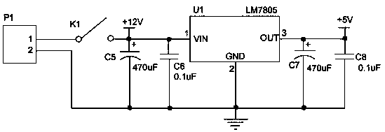
[0047] A power module 1, used to supply power to the device;

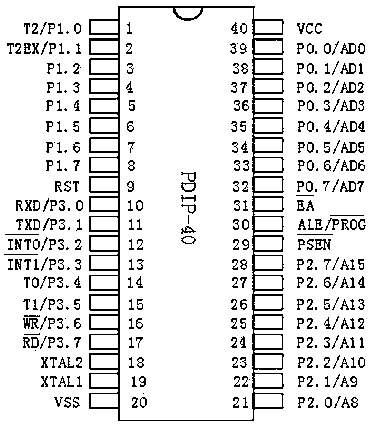
[0048] The single-chip microcomputer 2 is electrically connected with the power supply module 1, in order to realize the overall control of the device;

[0049] The constant current drive module 3 is electrically connected with the mains voltage, the single-chip microcomputer 2 and the LED lamp group 8, in order to provide a constant current for the LED lamp group 8;

[0050] The optical signal acquisition module 4 is used to regularly acquire optical signals;

[0051] The photoelectric signal conversion module 5 is electrically connected with the optical signal acquisition module 4 and the single-chip microcomputer 2, and is used to receive the optical signal and control the current output by the c...

Embodiment 2

[0078] According to the LED constant current driving device provided in the above embodiments, this embodiment provides a driving method for the LED constant current driving device.

[0079] A driving method for an LED constant current driving device, comprising the steps of:

[0080] S1, the single-chip microcomputer 2 scans the button to judge whether the manual signal sent by the button control module 6 is received, if so, execute step S2; otherwise, execute step S5;

[0081] S2. Determine the signal type of the manual signal. If the signal is increased, step S3 is performed; if the signal is decreased, step S4 is performed;

[0082] S3, the single-chip microcomputer 2 sends an increase signal to the constant current drive module 3, the output current of the constant current drive module 3 increases, and the brightness of the LED lamp group 8 increases;

[0083] S4, the single-chip microcomputer 2 sends a reduction signal to the constant current drive module 3, the output ...


PUM


Abstract

The invention provides an LED constant-current driving device and driving method, which is used for controlling display of an LED lamp group. The device comprises a power module, a singlechip microcomputer, a constant-current driving module, an optical signal acquisition module, a photoelectrical signal conversion module, a key control module and a brightness level display module, wherein the constant-current driving module is used for providing a constant current for the LED lamp group, the optical signal acquisition module is used for acquiring an optical signal at fixed time, the photoelectric signal conversion module is used for receiving the optical signal, controlling a current output from the constant-current driving module according to the optical signal and further controlling a current input into the LED lamp group so as to adjust the brightness of the LED lamp group, the key control module is used for outputting a manual signal to the singlechip microcomputer, the singlechipmicrocomputer is used for controlling an output current of the constant-current driving module according to a manual signal and further controlling the current input into the LED lamp group so as toadjust the brightness of the LED lamp group, and the brightness level display module is used for indicating a brightness level of the current LED lamp group. By the device and the method, the servicelifetime of an LED can be prolonged, and energy saving and environmental friendliness can be achieved very well.

Description

technical field [0001] The invention relates to the field of LEDs, in particular to an LED constant current driving device and a driving method thereof. Background technique [0002] LED constant current drive technology directly provides driving force for LED, which is equivalent to an engine. The development of LED constant current drive power supply technology is crucial to the development of LED related industries, and it is also of decisive significance. The main function of the LED constant current drive circuit is to convert the AC voltage into a DC power supply, and at the same time complete the matching with the voltage and current of the LED. With the linear decline of the power supply voltage of silicon integrated circuits, the working voltage of LEDs is more and more in the optimal range of the output voltage of the power supply. These constant current technologies will become more and more common. LED constant current driving technology is the core technology...

Claims


Application Information

Patent Timeline
Patent Type & Authority Applications(China)
IPC IPC(8): H05B33/08H05B44/00
CPCH05B45/10
Inventor 吴琼龙得花诸葛霞
Owner NINGBO UNIVERSITY OF TECHNOLOGY
Why Eureka
Try Eureka