Method for machining of ball tracks of inner races of constant velocity joints

A ball track and constant velocity joint technology, applied in the field of quick joints, can solve problems such as low efficiency, increase complexity and cost, and achieve the effect of reducing complexity and time requirements

Active Publication Date: 2019-09-13
SANDVIK INTELLECTUAL PROPERTY AB
View PDF8 Cites 1 Cited by
  • Summary
  • Abstract
  • Description
  • Claims
  • Application Information

AI Technical Summary

Problems solved by technology

[0007] In addition to the added complexity and cost of using such a specialized machine, the process tends to be less efficient than desired

Method used


Image

  • Method for machining of ball tracks of inner races of constant velocity joints
  • Method for machining of ball tracks of inner races of constant velocity joints
  • Method for machining of ball tracks of inner races of constant velocity joints

Examples


Embodiment Construction

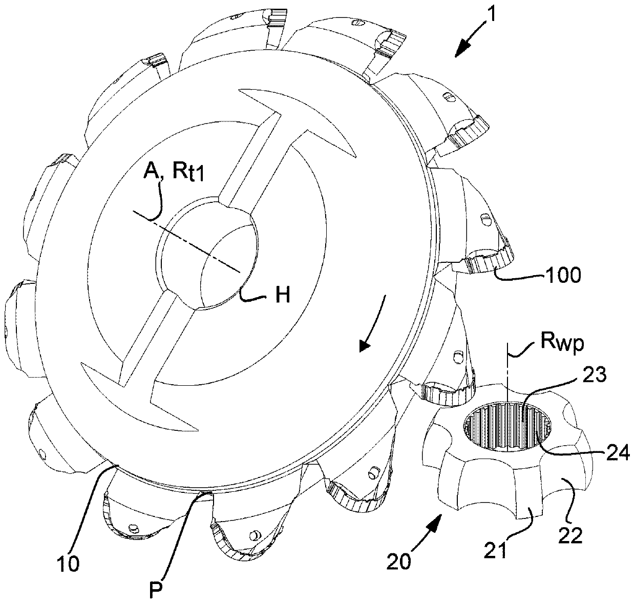
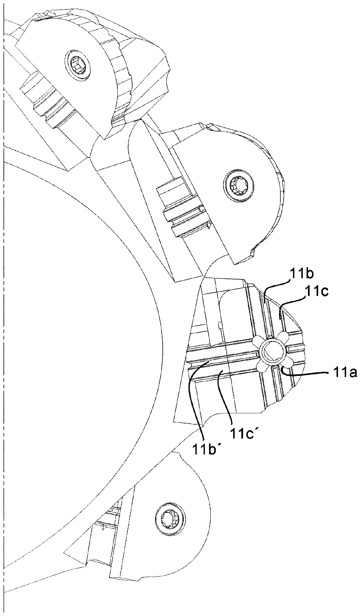
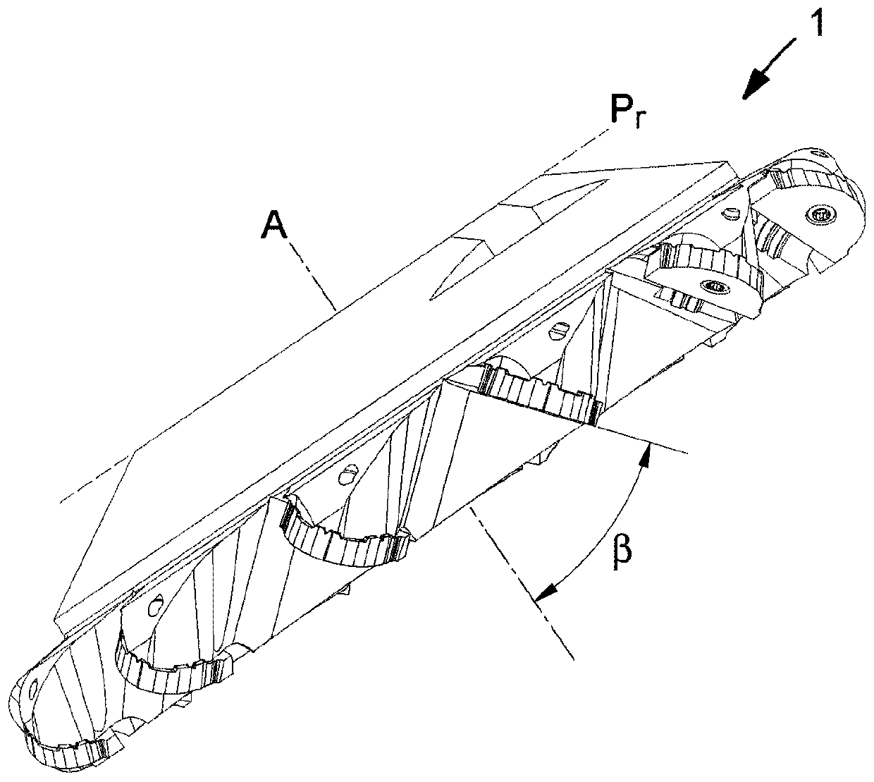
[0066] A power scraping tool 1 according to an exemplary embodiment is shown in a perspective view together with an exemplary workpiece 2 . The tool 1 comprises a tool body 10 which may be described as a ring or disk extending along an axial direction A which is aligned with an axis of rotation R of the tool and along a radial direction R t1 coincide. A plurality of cutting members in the form of replaceable inserts 100 are equally spaced along the perimeter P of the tool body.

[0067] The shown tool body 10 is a steel body and is suitable for attaching the tool by engagement by means of a central hole H to a spindle providing rotational movement to the tool.

[0068] The outer diameter of the tool body of the illustrated embodiment, ie the diameter at the periphery of the tool body, is about 150 mm. also, figure 1 The illustrated exemplary embodiment includes twelve cutting inserts 100 arranged along the periphery of the cutter body, the design of which will be described ...


PUM


Abstract

The present specification relates to a method for machining of ball tracks of an inner race of a constant velocity joint comprising the steps of providing a power skiving tool (1) having a plurality of cutting members and a first axis of rotation (Rt1), and a work piece (20) comprising an outer envelope surface (21) extending along an axis of rotation (Rwp), such that said first axis of rotation of said power skiving tool is arranged at a first distance from said axis of rotation of the work piece and oriented at a first angle (alpha) relative one another, applying a first rotational speed tosaid power skiving tool and a second rotational speed to said work piece and a relative movement between said work piece and said power skiving tool such that said cutting members engage said outer envelope surface to machine the ball tracks (22). The present specification also relates to a cutting insert and a power skiving cutting tool.

Description

technical field [0001] The present invention relates generally to the field of machining constant velocity joints. In particular, the invention relates to the machining of the ball tracks of the inner raceways of constant velocity joints. Background technique [0002] A constant velocity joint is a joint that transmits rotational motion from an input shaft to an output shaft at approximately a constant rotational speed regardless of the angle between the input shaft and output shaft. Such a joint may provide this function by, for example, an inner shell and an outer shell having a plurality of balls arranged in a raceway between the inner shell and the outer shell. The raceways may be divided into inner and outer raceways which are respectively arranged in the inner and outer shells so that the inner and outer shells respectively attached to the input shaft and the output shaft can surround their respective raceways while being at an angle relative to each other. The axis ...

Claims


Application Information

Patent Timeline
Patent Type & Authority Applications(China)
IPC IPC(8): B23C3/30B23B5/36B23F5/16B23Q27/00B23C5/08B23C5/14B23C3/32B23C5/22B23D15/14
CPCB23C3/30B23C3/32B23C5/08B23C5/14B23D15/14B23Q27/006B23C2200/0416B23C5/2213B23F5/163
Inventor 斯图雷·舍勒内·胡普费尔
Owner SANDVIK INTELLECTUAL PROPERTY AB
Why Eureka
Try Eureka