Al technical title is built by PatSnap Al team. It summarizes the technical point description of the patent document.
A blood component and centrifugal bag-type technology, applied in centrifuges and other directions, can solve problems such as failure to reset, easy storage of gas, and damage to membrane materials, and achieve the effects of reasonable structural design, low probability of damage, and simple structure
Inactive Publication Date: 2019-09-17
SHANGDONG ZHONGBAOKANG MEDICAL DEVICES
View PDF0 Cites 2 Cited by
Summary
Abstract
Description
Claims
Application Information
AI Technical Summary
This helps you quickly interpret patents by identifying the three key elements:
Problems solved by technology
Method used
Benefits of technology
Problems solved by technology
[0006] 1. The path is relatively complicated. Three monitoring boxes are used in a set of separators. In the actual use process, some flow paths are not used and are blocked with blind pipes. During the initialization process, the gas is not easy to discharge and easy to store. During the circulation process, air is easy to mix into the blood, which is risky for blood donors; and because of the use of three monitoring boxes, the pipelines are intricate and confusing, and the pipelines are easy to discount during the packaging and application process;
[0007] 2. The on-off of the flow path is controlled by the electromagnet under the monitoring box. The ejection force of the electromagnet ejector rod is relatively large, which is easy to cause damage to the membrane material; at the same time, because the electromagnet works at the lower part of the monitoring box, the actual operating state of the electromagnet Unable to observe, failure cannot be judged;
However, it often occurs that the negative pressure cannot be formed or the negative pressure is too small due to the tight seal, and the diaphragm cannot be reset, which affects the flow of blood and causes an alarm;
[0009] 4. There are 3 monitoring boxes, and 10 solenoid valves need to be installed on the equipment under each monitoring box to control the flow path. Together with the 4 electromagnets outside the monitoring box, there are 34 electromagnets in total, with high power and high probability of damage
Method used
Image
Click on the blue label to locate the original text in one second.
Reading with bidirectional positioning of images and text.
Examples
Embodiment Construction
[0047] The present invention will be further described below in conjunction with accompanying drawing:
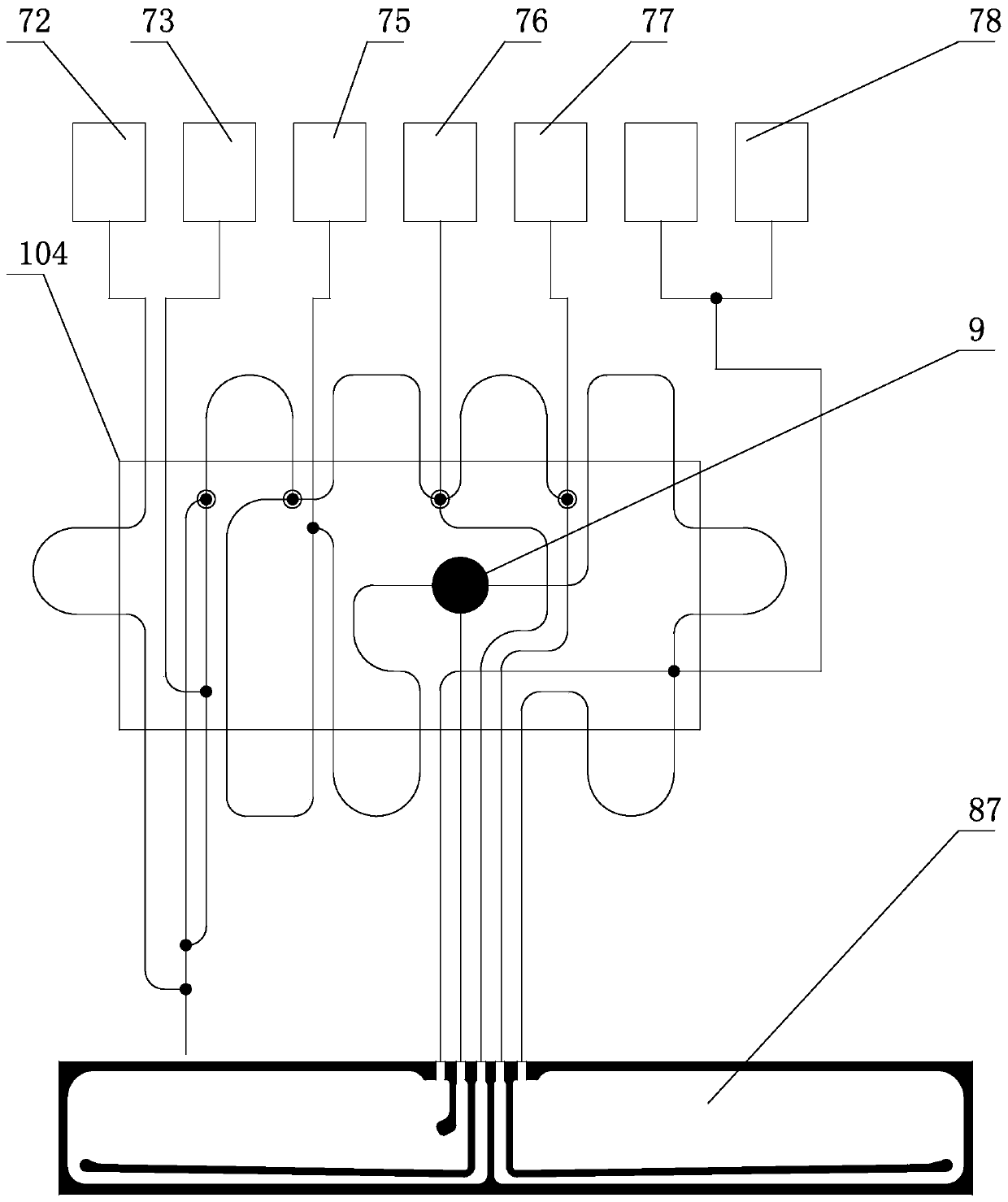
[0048] Such as Figure 1-Figure 14 , the centrifugal bag-type blood component separator of the present invention includes a double-layer flow path integration device 104, and the double-layer flow path integration device 104 communicates with the anticoagulant bag 72, the saline bag 73, the whole Blood bag 75, red blood cell bag 76, plasma bag 77, platelet bag 78 and centrifugal bag 87;
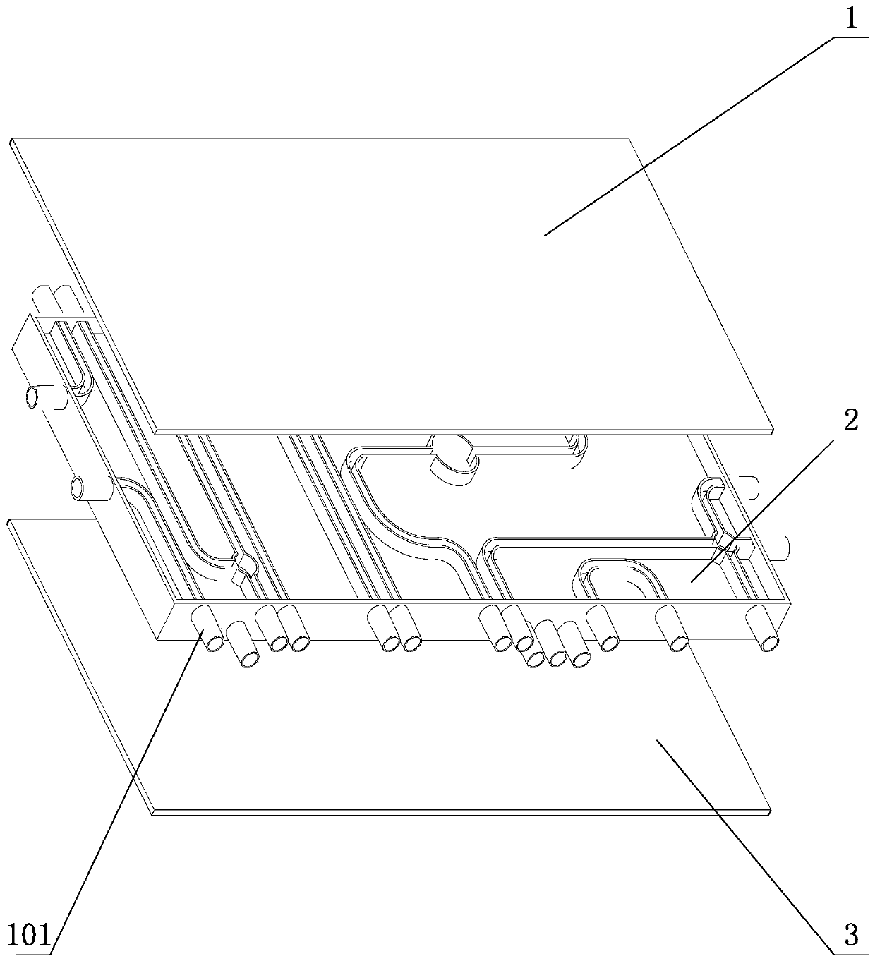
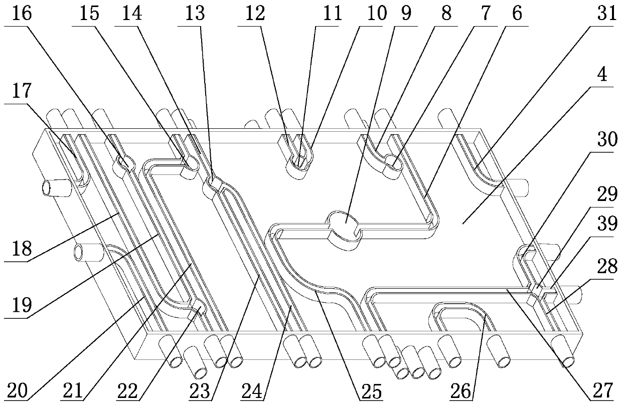
[0049] The double-layer flow path integrated device 104 includes an upper cover plate 1, an intermediate integrated body 2, and a lower cover plate 3 from top to bottom. The intermediate integrated body 2 includes an outer shell, and the inside of the outer shell is divided into an upper layer 4 and a lower layer 5 by a middle partition 102. , anticoagulant tubes, saline tubes 18, blood collection tubes 32, return blood vessels 19, centrifuge tubes, plasma tubes, red blood cell tubes, PRP...
PUM
Abstract
The invention belongs to the field of devices for blood component separation, and relates to a centrifugal bag type blood component separator. The centrifugal bag type blood component separator comprises a double-layer flow path integration device, the double-layer flow path integration device communicates with an anticoagulant bag, a saline bag, a whole blood bag, a erythrocyte bag, a plasma bag, a blood platelet bag and a centrifugal bag; the double-layer flow path integration device comprises an upper cover plate, a middle integrated body and a lower cover plate, wherein the middle integrated body comprises an outer shell; the inner part of the outer shell is partitioned into an upper layer and a lower layer by a middle partition plate; an anti-coagulant pipe, a blood collection tube, a blood return tube, a centrifugal tube, a plasma tube, an erythrocyte tube, a PRP tube, a blood platelet tube, a whole blood vessel and a mixing tube are distributed on the upper layer and the lower layer; and the outer periphery of the outer shell is provided with a plurality of connectors distributed in two layers, and the connectors communicate with corresponding pipelines arranged in the upper layer and the lower layer. According to the centrifugal bag type blood component separator, the structure is simple, only one double-layer flow path integration device is needed, the number of electromagnets needing to be used in cooperation with the whole device is small, the safety is high, the damage rate is low, and the service life is long.
Description
technical field [0001] The invention relates to a centrifugal bag type blood component separator, which belongs to the field of devices for separating blood components. Background technique [0002] At present, the widely used platelet collection device in domestic blood banks is the disposable centrifugal bag blood separator produced by Fresenius. This product is used in conjunction with the equipment. Relatively high, the consumption is increasing year by year, and the annual consumption is more than one million sets. The main part of this product is the monitoring box (such as Figure 15 and as Figure 16 ) and the centrifuge bag, and the structure of the monitoring box is complex, the working principle of the monitoring box is: [0003] (1) The monitoring box is an integrated channel, the shell is made of plexiglass, and the upper cover is made of plexiglass. The shell and the upper cover are assembled by ultrasonic welding. The soft PVC diaphragm is also welded togeth...
Claims
Application Information
Patent Timeline
Application Date:The date an application was filed.
Publication Date:The date a patent or application was officially published.
First Publication Date:The earliest publication date of a patent with the same application number.
Issue Date:Publication date of the patent grant document.
PCT Entry Date:The Entry date of PCT National Phase.
Estimated Expiry Date:The statutory expiry date of a patent right according to the Patent Law, and it is the longest term of protection that the patent right can achieve without the termination of the patent right due to other reasons(Term extension factor has been taken into account ).
Invalid Date:Actual expiry date is based on effective date or publication date of legal transaction data of invalid patent.