Impact wrench screwing angle and torque detection, reading and controlling method

An impact wrench and torque control technology, applied to wrenches, manufacturing tools, wrenches, etc., can solve problems such as continuous impact torque that is not easy to detect, achieve the effect of expanding the scope of use and solving precise control problems

Pending Publication Date: 2019-09-17
刘波
View PDF3 Cites 11 Cited by
  • Summary
  • Abstract
  • Description
  • Claims
  • Application Information

AI Technical Summary

Problems solved by technology

[0003] In order to solve the problem of the fixed tightening torque output of the impact motorized wrench, the present invention uses the principle that under a certain value of rotational impact force, a fixed value of the tightening angle will be generated when a certain bolt or nut is tightened, and will not be easy to detect. The continuous impact torque is converted into an easily detectable "effect" after the impact, that is, the tightening angle generated by the impact to tighten the bolt. Through the reading and detection of the tightening angle and tightening angular velocity, the impact wrench can output the tightening torque, Precise control of tightening angle and loosening circle number and angle

Method used


Image

  • Impact wrench screwing angle and torque detection, reading and controlling method
  • Impact wrench screwing angle and torque detection, reading and controlling method
  • Impact wrench screwing angle and torque detection, reading and controlling method

Examples


Embodiment Construction

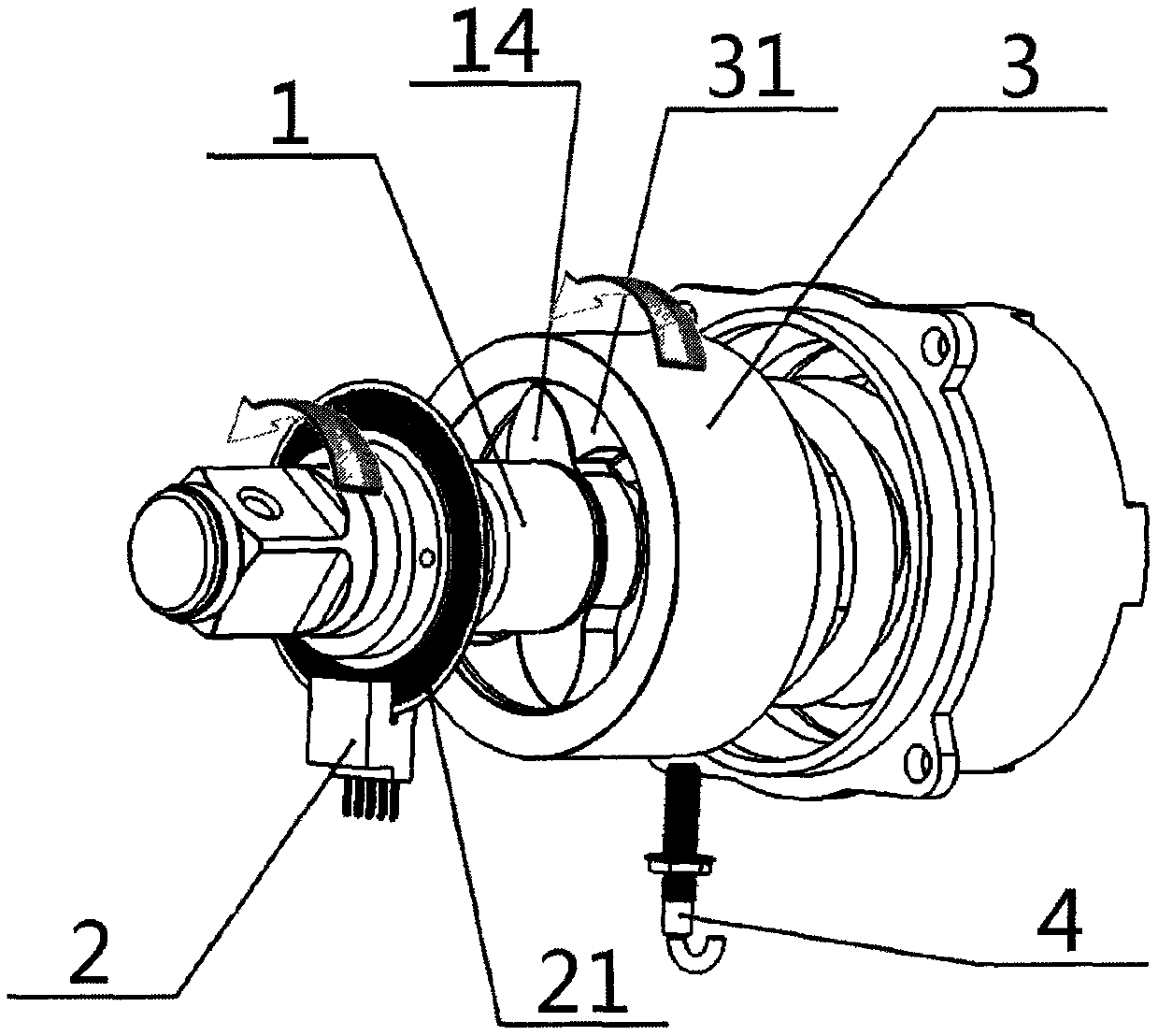
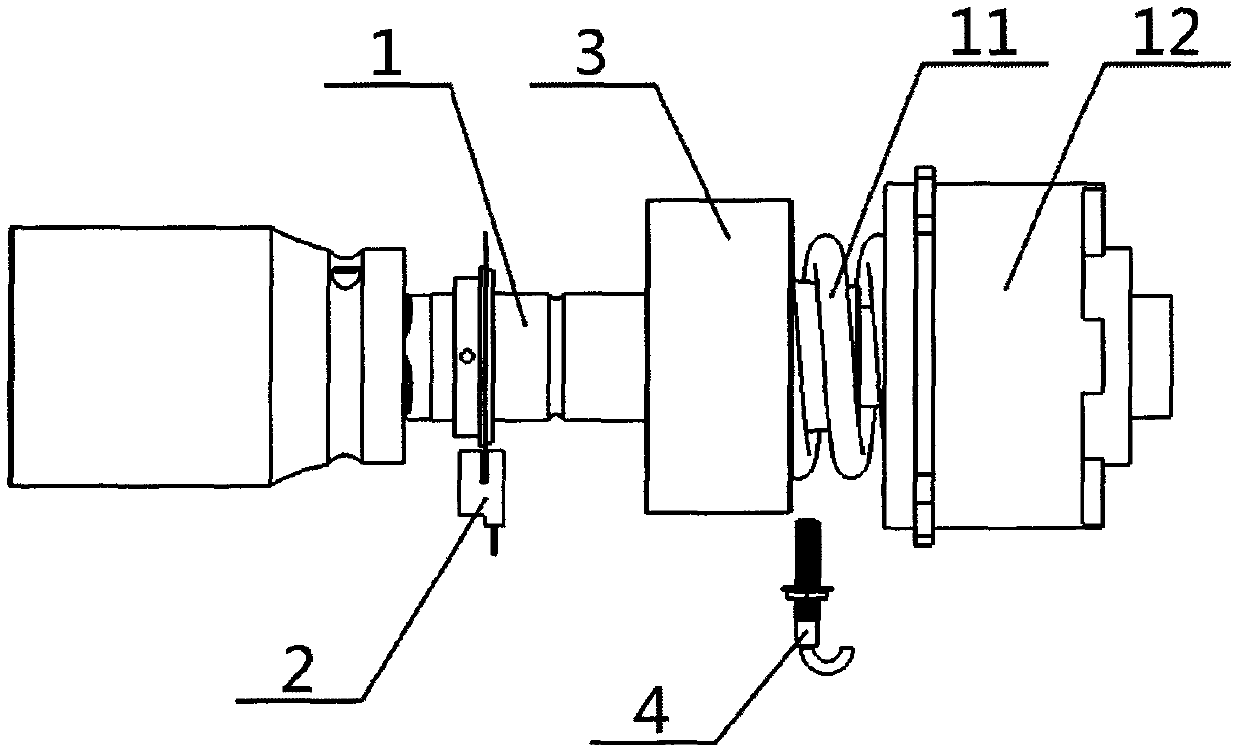
[0021] exist figure 1 and figure 2 Among them, on the output shaft 1 of the known impact wrench structure, the induction disc 21 of the angle detection device 2 is coaxially installed, which is used to output the rotation angle and angular velocity value of the output shaft of the driven part. The impact detection device 4 is installed vertically, which generates a pulse signal with the rotation and impact. After the wrench tightening action starts, the active part of the wrench drives the output shaft 1 of the driven part to rotate, outputting static torque, and the angle detection device 2 outputs the cumulative value of the tightening direction. The number of turns and the angle value are given to the torque controller 6.

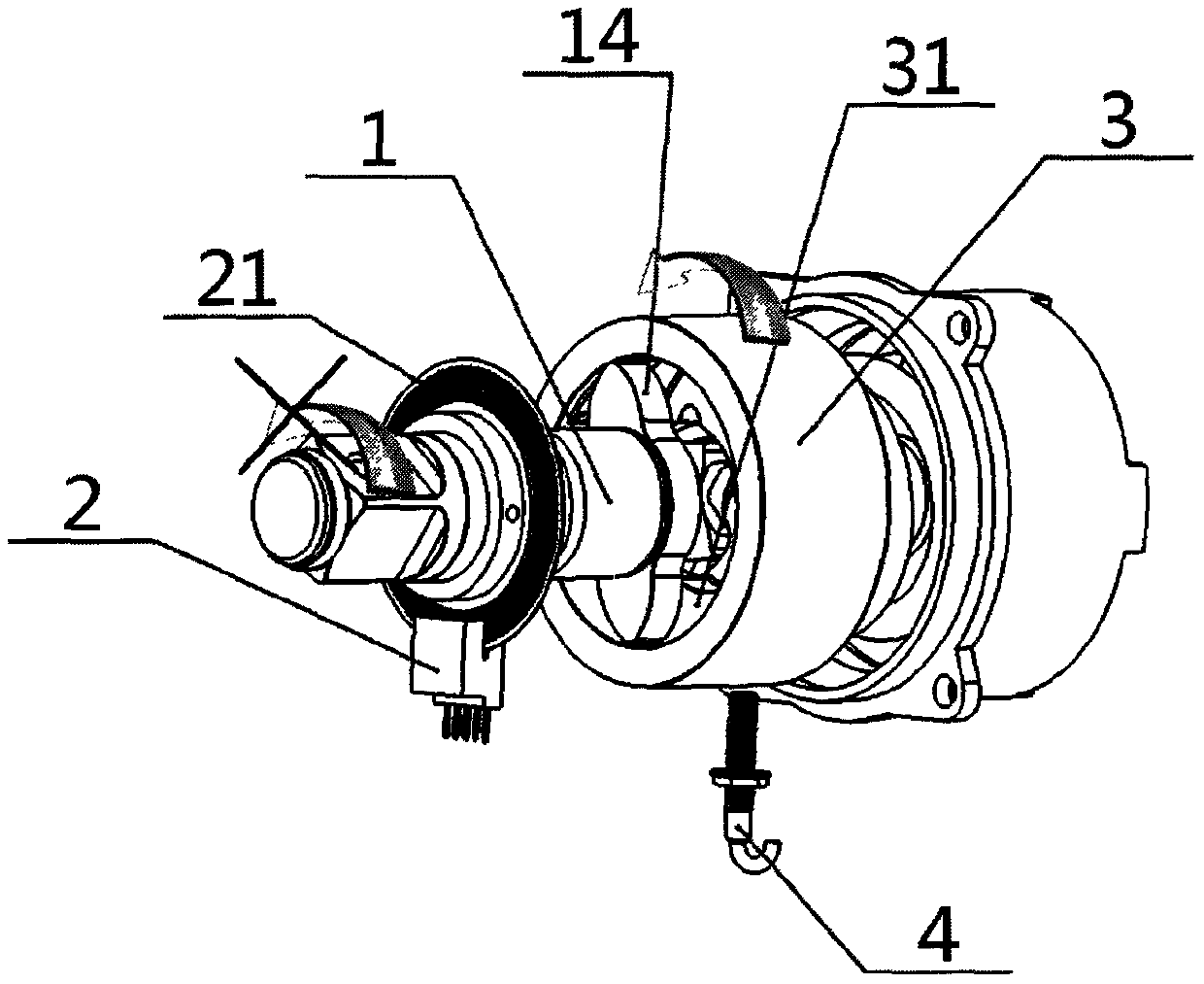
[0022] exist image 3 and Figure 4 In the process, when the wrench reaches the static torque output limit and turns into a rotational impact, the anvil 31 of the active block tooth-embedded structure is separated from the anvil 14 of the driven bloc...


PUM


Abstract

The invention provides an impact wrench screwing angle and torque detection, reading and controlling method. A detection device for detecting the rotation direction and the rotation angle of an output shaft is arranged on the output shaft of an impact wrench, and the detection device for detecting the impact action of an active impact member is vertically installed on the outer shell of the active impact member. When a screwing angle is used as a tightening stopping condition, a screwing angle of a screwing turning direction accumulated in a static twisting tightening stage is taken as A, an impact screwing angle at each time of the output shaft after an impact is started is used as delta alpha 1-delta alpha n, anti-vibration inverse screwing angles obtained after impact of the output shaft are recorded as the delta beta 1-delta beta n, a full-screwing angle is used as an An and is represented by a formula that An = A + delta alpha 1 + ...delta alpha n - delta beta 1 - ... delta beta n, a preset screwing angle is used as B, and a screwing action of a wrench is stopped when An is equal to B; and when a screwing torque is used as a stopping condition, when a full-screwing angle An with a certain torque requirement is reached after being verified, and when a corresponding delta alpha n angle of the nth impact is equal to a single impact screwing angle delta alpha n1 set by pre-calibration , the screwing action of the wrench is stopped, and the torque at the moment is the corresponding torque value when the full-screwing angle An is verified. An angle and the number of turns in the accumulated unscrewing direction are added together to be used as a stopping condition during unscrewing.

Description

technical field [0001] The invention relates to the field of precise control of the constant torque and constant tightening angle output of an impact motorized wrench, in particular to the structure of a numerically controlled impact wrench with constant torque and fixed tightening angle, and methods for detecting, reading and controlling the tightening angle and torque. Background technique [0002] Various types of constant torque motorized wrenches are widely used in various production lines and equipment manufacturing industries. In order to improve assembly quality, there are often clear requirements for thread assembly torque and tightening angle, especially in the high-end manufacturing industry. . Therefore, a large number of various types of motor wrenches with constant torque and fixed tightening angle are widely used in the above fields, but the cheapest and simplest traditional impact motor wrench among motor wrenches is currently technically unable to achieve ac...

Claims


Application Information

Patent Timeline
IPC IPC(8): B25B21/02B25B23/147B25B23/00
CPCB25B21/02B25B23/1475B25B23/00
Inventor 刘波
Owner 刘波
Why Eureka
Try Eureka