Processing system for garments

A processing system and clothing technology, which is applied in the field of clothing processing, can solve the problems that cannot be realized, cannot automatically add glue, etc., and achieve the effect of fast cloth pressing speed and high work efficiency

Active Publication Date: 2019-09-17
贵州雨林服饰有限公司
View PDF5 Cites 3 Cited by
  • Summary
  • Abstract
  • Description
  • Claims
  • Application Information

AI Technical Summary

Problems solved by technology

However, this equipment cannot automatically add glue between the two cloths that need to be pressed, and thus cannot realize the automatic and continuous cloth pressing work of automatically adding glue to the pressed cloth.

Method used


Image

  • Processing system for garments
  • Processing system for garments
  • Processing system for garments

Examples


specific Embodiment approach 1

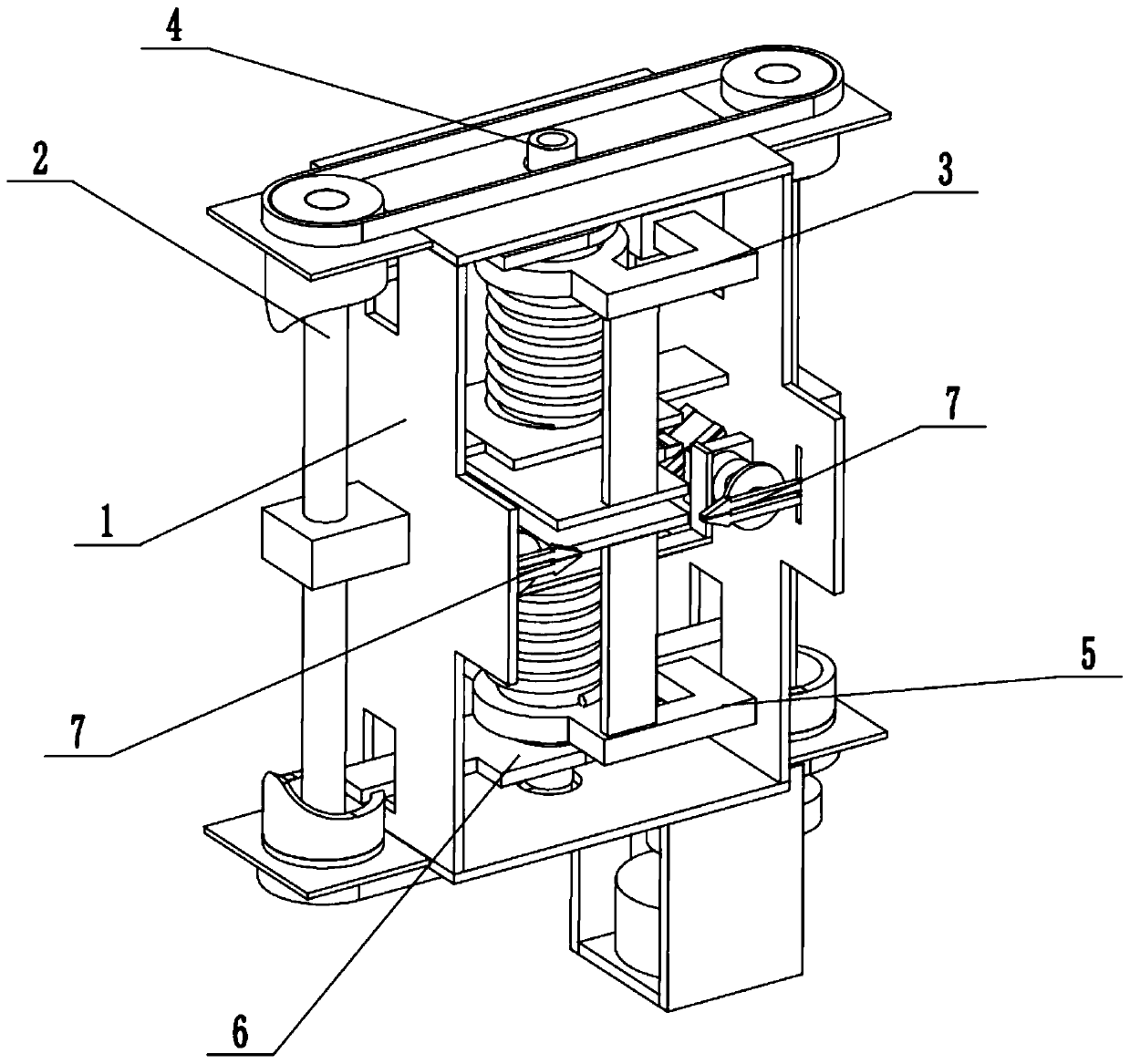
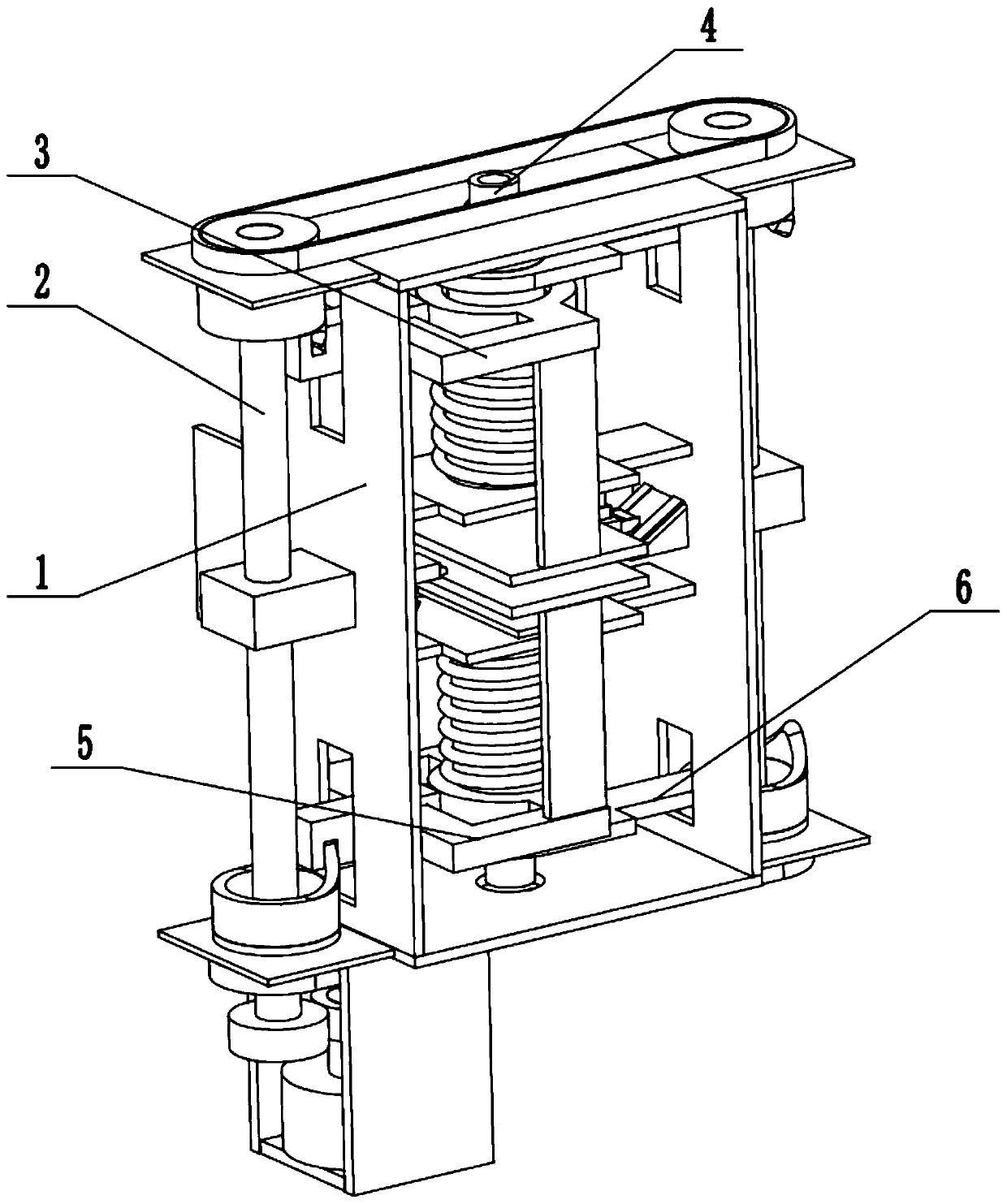
[0035] Such as Figure 1 to Figure 14 As shown, a garment processing system includes a base 1, a glue-adding and pressing-processing driver 2, an upper pressing device 3, an upper glue-adding device 4, a lower pressing device 5, a lower expanding driver 6 and two expanders 7 , the described glue-adding and pressing processing driver 2 is rotatably connected on the base 1, and the glue-adding and pressing-processing driver 2 is respectively connected with the upper presser 3, the upper gluer 4, the lower presser 5 and the lower expansion driver 6 The upper gluer 4 and the lower expansion driver 6 are respectively arranged in the upper presser 3 and the lower presser 5 through the clearance fit connection of the cam groove mechanism, and the upper presser 3, the upper gluer 4, and the lower presser Both the device 5 and the lower expansion driver 6 are slidably connected to the base 1, and the two dilators 7 are respectively slidably connected to the two ends of the inner wall o...

specific Embodiment approach 2

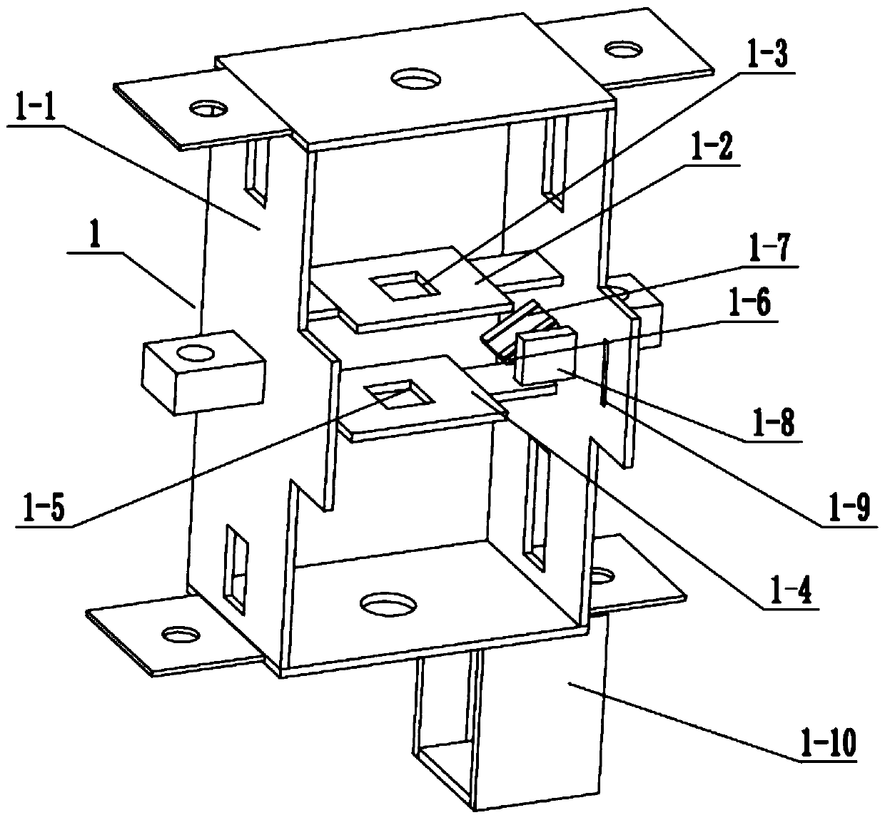
[0037] Such as Figure 1 to Figure 14 As shown, this embodiment further describes the first embodiment, the base 1 includes a four-frame frame 1-1, an upper support plate 1-2, an upper rectangular groove 1-3, a lower support plate 1-4, a lower Rectangular groove 1-5, two right-angle fixed seats 1-6, two inclined T-shaped chute 1-7, two fixed swivel seats 1-8, two rectangular chute 1-9 and motor fixing seat 1-10 , the upper support plate 1-2 and the lower support plate 1-4 are fixedly connected to the upper and lower sides of the inner wall of the four-frame frame 1-1 respectively, and the upper rectangular groove 1-3 and the lower rectangular groove 1-5 are set through respectively At the middle end of the upper support plate 1-2 and the lower support plate 1-4, two right-angle fixing seats 1-6 are respectively fixedly connected to the two sides of the middle end of the inner wall of the four-frame frame 1-1, and two inclined T-shaped chute 1-7 are respectively arranged on th...

specific Embodiment approach 3

[0039] Such as Figure 1 to Figure 14 As shown, this embodiment will further explain the second embodiment. The driver 2 for adding glue and pressing processing includes a servo motor 2-1, a driving gear 2-2, a driven gear 2-3, and a right rotation shaft 2- 4, right lower pulley 2-5, left lower pulley 2-6, left shaft 2-7, left upper pulley 2-8, right upper pulley 2-9, two left cams 2-10 and two right cams 2-11, so The servo motor 2-1 described above is fixedly connected to the motor holder 1-10, the driving gear 2-2 is fixedly connected to the drive shaft of the servo motor 2-1, and the driving gear 2-2 meshes with the driven gear 2-3 Transmission, the driven gear 2-3 is fixedly connected to the lower end of the right rotation shaft 2-4, the lower right pulley 2-5 is fixedly connected to the right rotation shaft 2-4, the left rotation shaft 2-7 and the right rotation shaft 2 -4 is respectively rotated and connected to the left and right ends of the four-frame frame 1-1; Lowe...


PUM


Abstract

The invention relates to the field of garment processing, and more particularly relates to a cutting system for garments. The system comprises a fabric unwinding roller, a machine frame, a fabric intermittent unwinding and winding driver, a style cutter, a fabric receiver, a fabric aligner and a recycling box; and the fabric unwinding roller is rotatably connected to the front end of the machine frame, the fabric intermittent unwinding and winding driver is rotatably connected in the machine frame, the style cutter is meshed with the fabric intermittent unwinding and winding driver, and the fabric intermittent unwinding and winding driver drives the style cutter to have reciprocating displacement on the machine frame in the vertical direction. The system provided by the invention has the beneficial effects of quickly and automatically cut batch-shaped and roller-shaped fabrics into a specified demand shape without manual operation, saving manpower, changing cutters with different shapes according to actual production requirements and being very convenient and quick.

Description

technical field [0001] The invention relates to the field of garment processing, more specifically a garment processing system. Background technique [0002] Patent No. CN201710657966.6 discloses a cloth pressing device for garment processing, including a base, a mounting plate is provided on the top side of the base, and a first chute is provided inside the mounting plate along its length direction. The first chute A spring is sleeved inside the spring, and both ends of the spring are connected with a fixed plate, and one end of the two sets of fixed plates extends out of the first chute, one side of the base is welded with a support plate, and the end of the support plate away from the base is welded with a horizontal setting The top plate, the side of the top plate close to the base is provided with a second chute along its length direction, the inside of the second chute is sleeved with a first slider and a second slider, and the first slider is far away from a side of t...

Claims


Application Information

Patent Timeline
IPC IPC(8): B32B37/10B32B37/12
CPCB32B37/10B32B37/12B32B37/1284
Inventor 周保文
Owner 贵州雨林服饰有限公司
Why Eureka
Try Eureka