A centrifugal spinning device

A spinning device and spinning device technology, applied in the field of centrifugal spinning spinning device, can solve problems such as easy leakage, rising pipeline pressure, unrealized technology, etc., and achieve the effect of improving work efficiency and reducing labor intensity

Active Publication Date: 2021-10-26
WUHAN TEXTILE UNIV +1
View PDF6 Cites 0 Cited by
  • Summary
  • Abstract
  • Description
  • Claims
  • Application Information

AI Technical Summary

Problems solved by technology

[0003] In order to realize continuous feeding, the invention patent with application number CN201510621573.0 provides a continuous feeding device suitable for solution centrifugal spinning, including a motor and a spinneret, the motor is set on the frame, and one end of the drive shaft is connected to The other end is connected with the spinneret; the device also includes a hose fixing base fixed on the frame through a support rod, which has a longitudinal through hole inside; a bearing is provided at both ends of the through hole, so The transmission shaft is installed in the flange bearing and coincides with the center line of the through hole; a rubber hose passes through the oblique through hole on the side of the hose holder, and the feed port of the rubber hose is connected to the injection The outlet of the pump, its discharge port is suspended into the hollow cavity of the spinneret, and does not contact the inner wall of the cavity or the drive shaft; the problem with this feeding device is that the spinneret is connected to the drive shaft to achieve rotation, and the rubber The hose hangs in the air and extends into the hollow cavity of the spinneret, but the rubber hose is fixed on the hose holder, and the hose holder does not rotate, making this technology impossible
[0004] The patent with the application number CN201820388681.7 provides a centrifugal electrospinning device, including a centrifugal spinning nozzle and a driving mechanism for driving the centrifugal spinning nozzle, and the centrifugal spinning nozzle is connected to a spinning solution delivery device; The driving mechanism includes a centrifugal shaft located at the bottom of the centrifugal spinning nozzle, and the spinning solution delivery device includes a feeding pump, a feeding pipeline and a storage bin, one end of the feeding pipeline is connected to the storage bin, and the other end is It is connected with the lower end of the centrifugal shaft; the centrifugal shaft is a hollow tube, and the bottom of the liquid storage chamber in the centrifugal spinning nozzle communicates with the upper end of the centrifugal shaft; this device uses a feeding pump to spin the The solution is pumped into the liquid storage cavity in the centrifugal spinning nozzle through the feed pipe. Due to the structural limitation, the feeding pump must continuously supply the material. The pressure of the feeding pump is usually in a fluctuating state, so the fluctuating pressure of the feeding pump will be directly transmitted Into the centrifugal spinning nozzle, the quality of centrifugal spinning is affected; in addition, because the feeding pump is directly connected to the liquid storage chamber in the centrifugal spinning nozzle through the feeding pipeline, the feeding pump makes the entire pipeline pressure Elevated, the centrifugal shaft is in a state of high-speed rotation, while the feed pipe is in a static state, so that the connection between the centrifugal shaft and the feed pipe is prone to leakage under pressure

Method used


Image

  • A centrifugal spinning device
  • A centrifugal spinning device
  • A centrifugal spinning device

Examples


Embodiment 1

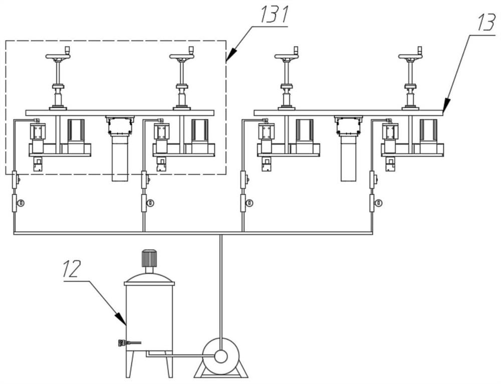
[0046] Such as figure 1 Shown, a kind of centrifugal spinning spinning device comprises feeding device 12 and spinning device 13; Described feeding device 12 feeds material to described spinning device 13; Described spinning device 13 carries out centrifugal spinning; The spinning device 13 includes at least one set of spinning units 131, and the number of spinning units 131 is selected according to the thickness requirement of the centrifugally spun fiber web.

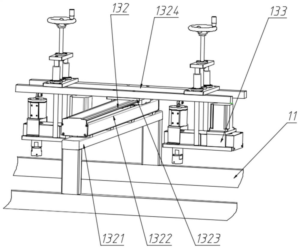
[0047] Such as figure 2 As shown, the spinning unit 131 includes a traversing device 132 and two sets of spinning devices 133 symmetrically installed on both sides of the traversing device 132; the traversing device 132 is fixedly installed on the frame 11; The moving device 132 drives the spinning device 133 to perform a horizontal reciprocating movement above the collecting device 14, so that the spinning fibers ejected from the spinning device 133 cover the entire collecting device 14.

[0048] The traversing de...

Embodiment 2

[0066] The difference with embodiment 1 is that, in the spinner device 133 in embodiment 2, at least one spinneret 1354 is installed on its said spinneret 1340; The shape of shown spinneret is as follows Figure 7 As shown, its inner diameter gradually becomes smaller to form a cone; the spinning solution in the spinneret 1340 is ejected through the spinneret 1354 .

Embodiment 3

[0068] The difference with embodiment 1 is that, in the spinner device 133 in embodiment 3, at least one spinneret 1354 is installed on its said spinneret 1340; The shape of shown spinneret is as follows Figure 8 As shown, its structure is in the form of steps; the spinning solution in the spinneret 1340 is ejected through the spinneret 1354 .


PUM


Abstract

The invention discloses a spinneret for centrifugal spinning. A buffer tank for buffering is installed between the spinneret and a flow pump. The flow pump supplies material to the buffer tank, and the spinning solution in the buffer tank flows into the spinneret by its own weight. In the device, the influence of the pressure fluctuation of the flow pump and the leakage problem are avoided; the invention adopts the pipeline control technology to realize that a set of feeding device automatically feeds materials to multiple buffer tanks at the same time, greatly improving the work efficiency and reducing the labor intensity of personnel; the invention A traverse device is used to drive the spinneret to reciprocate horizontally above the collection belt along the width direction of the collection belt, so that the fibers ejected from the spinneret cover the entire collection belt to realize wide-width nonwoven production.

Description

technical field [0001] The invention relates to the technical field of textiles, in particular to a centrifugal spinning spinning device. Background technique [0002] At present, for centrifugal spinning technology, the forming mechanism of its fibers has been deeply studied, and the technical problem to be solved is how to realize the continuous mass production of centrifugal spinning; the traditional centrifugal spinning feeding system is a semi-continuous feeding system , that is, each time the centrifugal spinning experiment is carried out, the spinning solution is input into the liquid storage cavity of the spinneret through the syringe, and the spinning process is in a discontinuous manner. [0003] In order to realize continuous feeding, the invention patent with application number CN201510621573.0 provides a continuous feeding device suitable for solution centrifugal spinning, including a motor and a spinneret, the motor is set on the frame, and one end of the drive...

Claims


Application Information

Patent Timeline
Patent Type & Authority Patents(China)
IPC IPC(8): D01D5/18D01D1/06
CPCD01D1/06D01D5/18
Inventor 刘欣吴龙涛徐卫林李晨林勇张科王亚飞陈太照王平顾绍金
Owner WUHAN TEXTILE UNIV
Why Eureka
Try Eureka