Integrated finished steel structure door sleeve product

A steel structure and door cover technology, applied in the direction of door leaves, windows/doors, building components, etc., can solve the problems of inconvenient maintenance, affecting the overall effect, and inadequate construction, etc., to achieve convenient transportation and installation, beautiful overall effect, and durability high intensity effect

Inactive Publication Date: 2019-09-17
CHINA RAILWAY URBAN PLANNING & DESIGN INST
View PDF5 Cites 0 Cited by
  • Summary
  • Abstract
  • Description
  • Claims
  • Application Information

AI Technical Summary

Problems solved by technology

[0002] In recent years, with the continuous development and expansion of the scale of urban construction, it is often necessary to add various types of equipment rooms in the construction of buildings, the equipment rooms of above-ground and underground buildings, and the treatment of the waterproof threshold steps of the roof rooms. , has also become an increasingly prominent problem: steps are often missed during the construction process due to the negligence of construction personnel, or concrete and brick steps are damaged in actual use and affect normal use
[0003] The disadvantages of the threshold steps of the above-mentioned roof-out room and equipment room are: 1. During the construction process, the construction personnel of the construction unit are prone to cut corners and materials, and the construction is not in place, resulting in potential safety hazards; 2. The threshold steps of the waterproof room are separated. The construction is easy to be damaged, inconvenient to maintain, and has defects in use; 3. The threshold steps are fixed and occupy indoor space; 4. The traditional threshold step construction is irregular and unsightly, which affects the overall effect

Method used


Image

  • Integrated finished steel structure door sleeve product
  • Integrated finished steel structure door sleeve product
  • Integrated finished steel structure door sleeve product

Examples


specific Embodiment 1

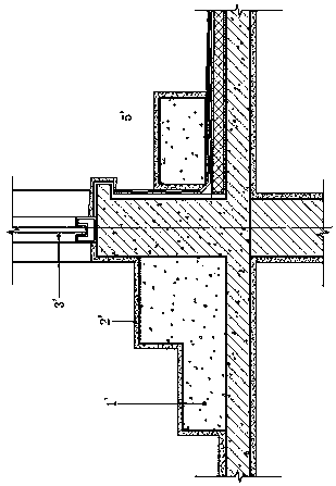
[0021] refer to image 3 , image 3 It is a structural schematic diagram of a specific embodiment of the present invention.

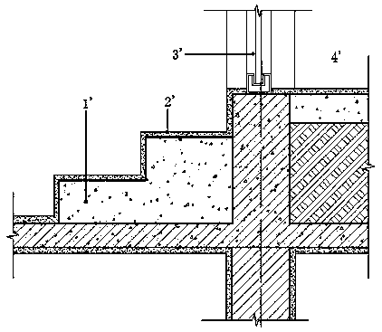
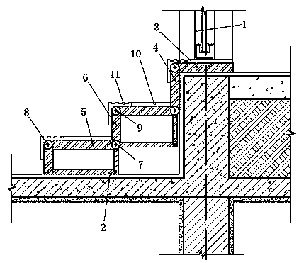
[0022] This embodiment provides an integrated steel structure door cover for an underground construction equipment room, including a steel structure door body 1, a hinge pedal and a hinge bracket 2; The installation and fixing part 3, the installation and connection part 4 hinged with the installation and fixing part 3, and the folding step part that is hinged with the installation and connection part 4, the folding steps are composed of several step components, each of the steps The assembly includes a step panel 5, a step support plate 6, and a step hinge shaft 7 that hinges the step panel 5 and the step support plate 6, and the side of the step panel 5 parallel to the step hinge axis 7 The edge is provided with a panel hinge shaft 8, and the side edge of the step support plate 6 parallel to the step hinge axis 7 is provided with a support plate hin...


PUM


Abstract

The invention discloses an integrated finished steel structure door sleeve product, which comprises a steel structure door body, a hinge pedal and hinge supports. The hinge pedal comprises a mounting fixing part, a mounting connecting part and a folding step part which are fixedly arranged at the bottom of the steel structure door body; the folding step part is composed of a plurality of step assemblies, and each step assembly comprises a step panel, a step supporting plate and a step hinge shaft; panel hinge shafts are arranged at the edges of the sides, parallel to the step hinge shafts, of the step panels, and supporting plate hinge shafts are arranged at the edges of the sides, parallel to the step hinge shafts, of the step supporting plates; and the bottom of each step assembly is provided with the corresponding set of hinge supports, and each set comprises the two corresponding hinge supports which are mutually hinged, wherein the edges of the sides, parallel to hinged shafts, of the two hinge supports are connected with the corresponding panel hinge shaft and the corresponding supporting plate hinge shaft correspondingly. Doorsill steps of a waterproof room can be obtained without the need of concrete construction work.

Description

technical field [0001] The invention relates to the technical field of a steel structure door cover for a waterproof room on the ground, underground and roof of a building, in particular to an integrated finished steel structure door cover. Background technique [0002] In recent years, with the continuous development and expansion of the scale of urban construction, it is often necessary to add various types of equipment rooms in the construction of buildings, the equipment rooms of above-ground and underground buildings, and the treatment of the waterproof threshold steps of the roof rooms. , has also become an increasingly prominent problem: steps are often missed during the construction process due to the negligence of construction personnel, or concrete and brick steps are damaged in actual use and affect normal use. In the prior art, the threshold step method of the roof room and the equipment room is as follows: figure 1 and figure 2 Shown: figure 1 and 2 1' is t...

Claims


Application Information

Patent Timeline
Patent Type & Authority Applications(China)
IPC IPC(8): E06B1/34E06B1/70E06B3/70
CPCE06B1/34E06B1/70E06B3/70E06B2001/707
Inventor 卞青查亦林
Owner CHINA RAILWAY URBAN PLANNING & DESIGN INST
Why Eureka
Try Eureka