Multicamera system and laser radar combined system and combined calibration method thereof

A laser radar and joint system technology, applied in the computer field, can solve problems such as inability to complete camera internal reference and external reference, calibration, multi-camera system with less common field of view, etc., to save calibration time and process, ensure accuracy, and simplify calibration steps Effect

Active Publication Date: 2019-09-17
宁波智能装备研究院有限公司
View PDF5 Cites 16 Cited by
  • Summary
  • Abstract
  • Description
  • Claims
  • Application Information

AI Technical Summary

Problems solved by technology

[0004] The purpose of the present invention is to provide a multi-camera system and lidar joint system and its joint calibration method to solve the problem that the existing multi-camera calibration requires a common field of view. In a multi-camera system, there are few common fields of view or no field of view and the camera cannot be completed. Calibration of internal and external parameters, and simplify the method of joint calibration of multi-camera system and lidar

Method used


Image

  • Multicamera system and laser radar combined system and combined calibration method thereof
  • Multicamera system and laser radar combined system and combined calibration method thereof
  • Multicamera system and laser radar combined system and combined calibration method thereof

Examples


Embodiment 1

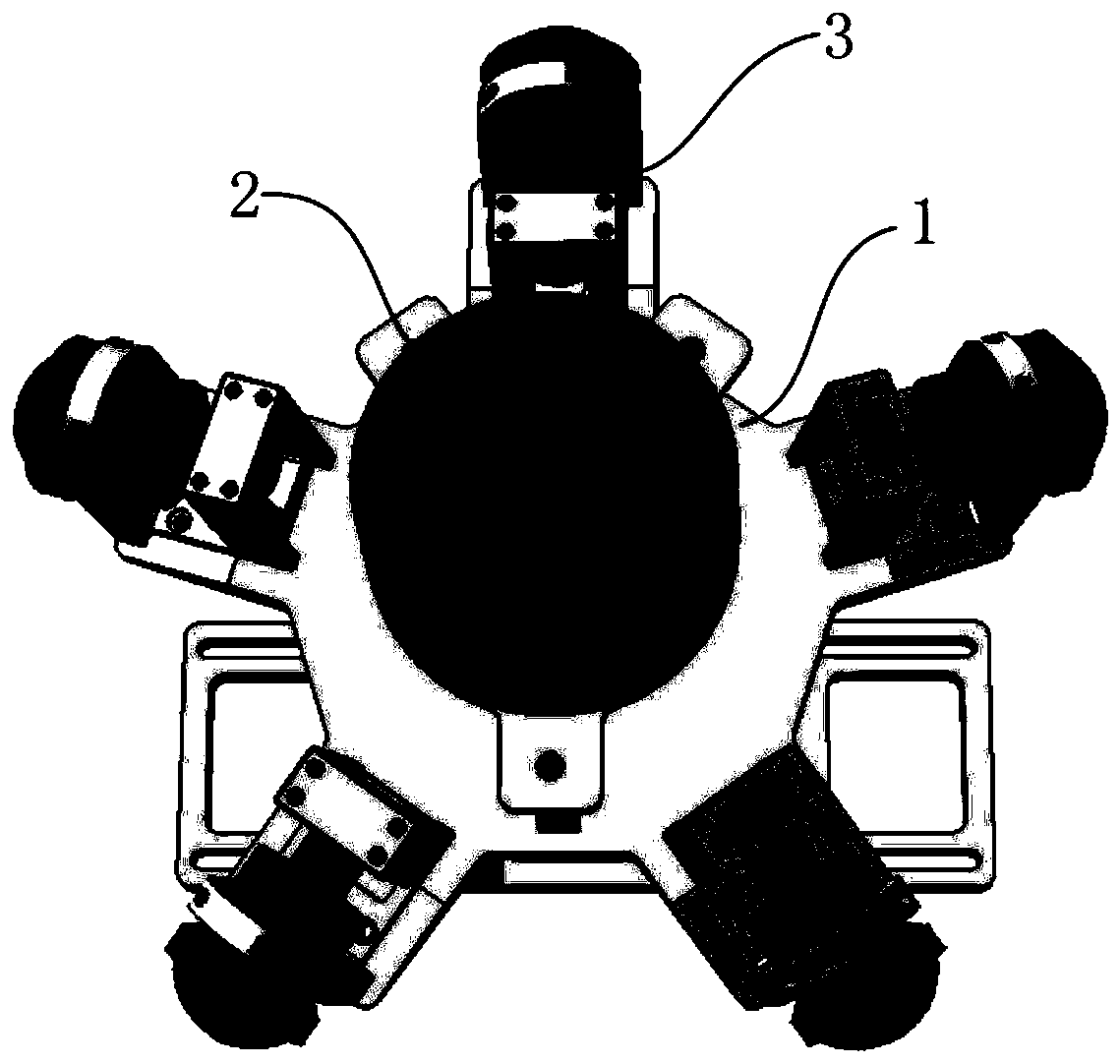
[0033] Such as Figure 1-3 As shown, the present invention discloses a multi-camera system and laser radar combined system, said combined system includes five sets of industrial cameras 3 and one set of laser radar 2, industrial cameras 3 and laser radar 2 are installed on the fixed bracket 1 , the industrial cameras 3 are installed on the outside of the laser radar 2 in an equicentric distribution with the laser radar 2 as the center.

[0034] Among them, the lidar 2 is a 2.5D lidar or a 3D lidar, and the vertical field of view of the lidar 2 is 10°-40°.

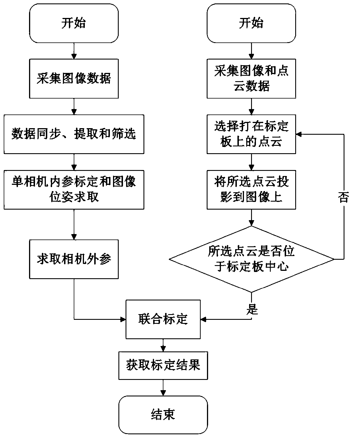
[0035] The present invention also discloses a multi-camera system and lidar joint calibration method, which adopts the above-mentioned joint system, and specifically includes the following steps:

[0036] S1. Install the fixed joint system, turn on the synchronous shooting function of the industrial camera 3, place the special calibration board outside the joint system, adjust the distance between the special calibration b...


PUM


Abstract

The invention relates to the technical field of computers and discloses a multicamera system and laser radar combined calibration method. A particularly generated calibration plate is used, as long as two adjacent cameras can simultaneously shoot a part of the calibration plate, the internal reference and the external reference of the multicamera can be solved, when the cameras of the multicamera system meet the requirement that two adjacent cameras can shoot the calibration plate at the same time, the calibration of the multicamera system can be completed, and the calibration of the multicamera system and the laser radar is completed in combination with the calibration of a single camera and the laser radar, thereby omitting the steps that the laser radar and the cameras are used for collecting data and selecting point cloud, simplifying the calibration step, saving the time and process for calibration on the premise of guaranteeing the precision, and solving the problem that the calibration of the multicamera system cannot be completed under the condition that the adjacent cameras do not have a common view field or the common view field is small.

Description

technical field [0001] The invention relates to the field of computer technology, in particular to a multi-camera system and a lidar joint system and a joint calibration method thereof. Background technique [0002] Most of the information that humans receive during driving comes from vision, such as traffic signs, road signs, traffic signals, etc. These visual information become the main decision-making basis for human drivers to control vehicles. In autonomous driving, the camera replaces the human visual system as one of the sensors for traffic environment perception. Compared with other sensors, the method of installation and use of the camera is simple, the amount of image information obtained is large, the input cost is low, and the scope of action is wide. However, the camera is easily affected by the light, and the shooting effect is poor in places with poor light or sudden changes in light. Another commonly used sensor in autonomous driving is lidar. Lidar works ...

Claims


Application Information

Patent Timeline
Patent Type & Authority Applications(China)
IPC IPC(8): G01S7/497G06T7/80
CPCG01S7/497G06T7/80
Inventor 于兴虎王晨宇
Owner 宁波智能装备研究院有限公司
Why Eureka
Try Eureka