Intelligent optical cable monitoring system and method with optical cable protection function

A technology of optical cable protection and monitoring system, which is applied in the field of optical fiber communication, can solve the problems of increasing costs and achieve the effect of protection and saving operating costs

Pending Publication Date: 2019-09-17
武汉孚晟科技有限公司 +1
View PDF0 Cites 3 Cited by
  • Summary
  • Abstract
  • Description
  • Claims
  • Application Information

AI Technical Summary

Problems solved by technology

In this way, two sets of OTDR systems need to be set up, which increases the cost

Method used


Image

  • Intelligent optical cable monitoring system and method with optical cable protection function
  • Intelligent optical cable monitoring system and method with optical cable protection function
  • Intelligent optical cable monitoring system and method with optical cable protection function

Examples


Embodiment 1

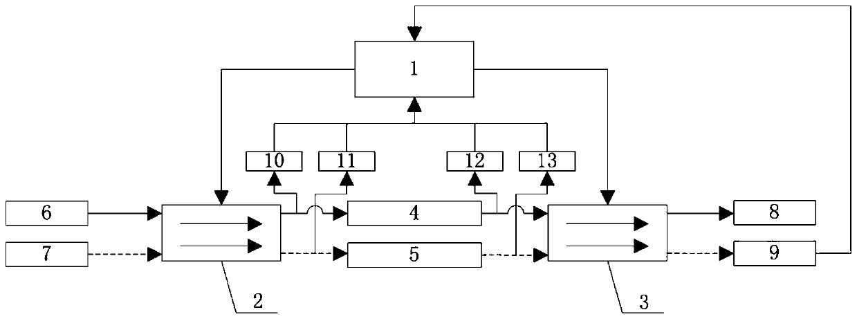
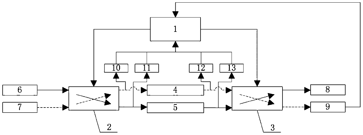
[0023] Such as figure 1 , 2 As shown, this embodiment provides an intelligent optical cable monitoring system with an optical cable protection function, including: a network management unit 1, a first optical switch 2, a second optical switch 3, a main optical cable 4, a backup optical cable 5, an OTDR module and multiple an optical power monitoring unit; the first optical switch 2, the second optical switch 3, the OTDR module, and a plurality of optical power monitoring units are respectively connected to the network management unit 1; the two input ends of the first optical switch 2 are respectively used For inputting service optical pulses and test optical pulses; the two output ends of the first optical switch 2 are respectively connected to the input ends of the main optical cable 4 and the backup optical cable 5; the output ends of the main optical cable 4 and the backup optical cable 5 are respectively connected to the first Two input ends of two optical switches 3; tw...

Embodiment 2

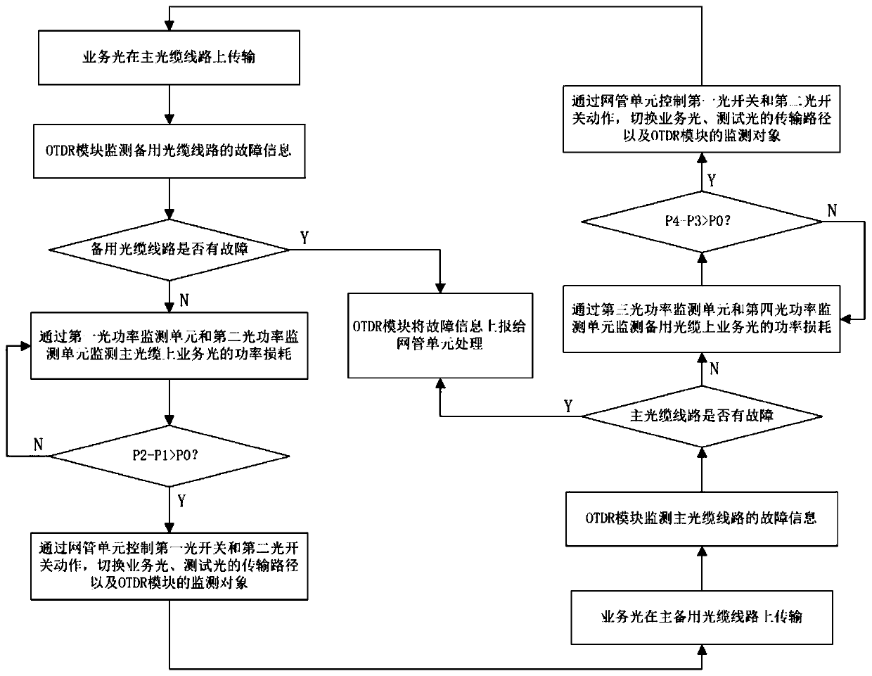
[0030] Such as image 3 As shown, this embodiment provides an intelligent optical cable monitoring method with an optical cable protection function, the specific method is:

[0031] When the service optical pulse is transmitted on the main optical cable 4 line, the OTDR module is connected to the spare optical cable 5 line; the service optical pulse emitted by the service optical transmitter 6 is coupled into the main optical cable 4 through the first optical switch 2, and then passed through the second The optical switch 3 is transmitted to the user terminal 8; the signal transmitting end 7 of the OTDR module transmits a test optical pulse, and the test optical pulse is coupled into the spare optical cable 5 through the first optical switch 2, and then transmitted to the signal reception of the OTDR module through the second optical switch 3 Terminal 9; monitor the fault information of the backup optical cable 5 through the OTDR module; monitor the power loss of the service o...


PUM


Abstract

The invention discloses an intelligent optical cable monitoring system and method with an optical cable protection function. The intelligent optical cable monitoring system comprises a network management unit, a first optical switch, a second optical switch, a main optical cable, a standby optical cable, an OTDR module and a plurality of optical power monitoring units. Two input ends of the first optical switch are respectively used for inputting a service optical pulse and a test optical pulse; two output ends of the first optical switch are respectively connected with input ends of the main optical cable and the standby optical cable; the output ends of the main optical cable and the standby optical cable are respectively connected with two input ends of the second optical switch; two output ends of the second optical switch are respectively connected with a user end and a signal receiving end of the OTDR module; the plurality of optical power monitoring units are respectively used for monitoring line loss of the main optical cable or the standby optical cable; the OTDR module is used for monitoring fault information of the main optical cable or the standby optical cable; wherein the first optical switch is used for switching input optical pulses of the main optical cable and the standby optical cable, and the second optical switch is used for switching output paths of the main optical cable and the standby optical cable.

Description

technical field [0001] The invention belongs to the technical field of optical fiber communication, in particular to an intelligent optical cable monitoring system and method with an optical cable protection function. Background technique [0002] With the development of optical fiber communication technology and the continuous expansion of optical fiber communication networks, the maintenance of optical fiber cables is becoming more and more urgent. It is very important to implement real-time protection and monitoring of optical cable lines. [0003] The optical cable monitoring system uses the optical time domain reflectometer (OTDR) to realize the automatic monitoring of the optical cable line and locate the fault point of the optical fiber by testing the backscattering curve of the optical fiber; At present, the protection is mainly realized through the automatic switching protection technology of optical fiber lines; through the simple bridge of the main and backup rout...

Claims


Application Information

Patent Timeline
Patent Type & Authority Applications(China)
IPC IPC(8): H04B10/032H04B10/071H04B10/079
CPCH04B10/032H04B10/071H04B10/0791H04B10/07955
Inventor 王新陈妍孙志峰蒋燕周智睿
Owner 武汉孚晟科技有限公司
Why Eureka
Try Eureka