Display device for visual communication design

A display device and visual technology, applied in applications, home appliances, display stands, etc., can solve the problems of inconvenient adjustment of the display angle and inability to display exhibits, etc., achieve a stable and efficient adjustment process, good clamping and stability effects, and increase the number of exhibits Effect

Inactive Publication Date: 2019-09-20
ZHONGBEI UNIV
View PDF7 Cites 18 Cited by
  • Summary
  • Abstract
  • Description
  • Claims
  • Application Information

AI Technical Summary

Problems solved by technology

However, the device is inconvenient to adjust the display angle of the exhibits and cannot fully display the exhibits. Therefore, a display device for visual communication design is now provided to solve the above technical problems

Method used


Image

  • Display device for visual communication design
  • Display device for visual communication design
  • Display device for visual communication design

Examples


Embodiment 1

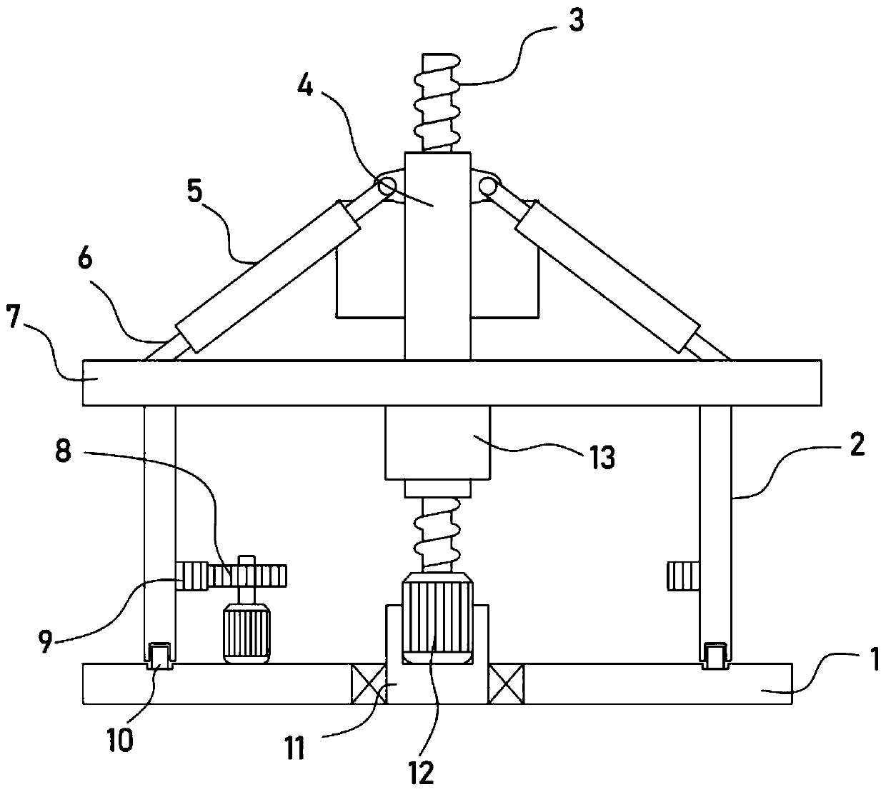
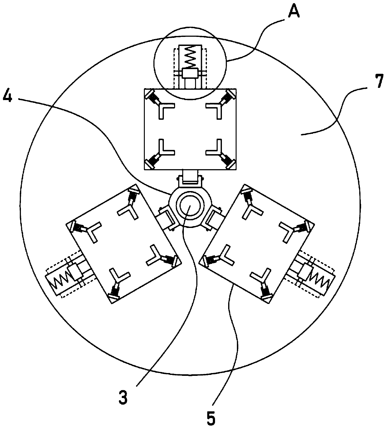
[0024] see Figure 1-5 , a display device for visual communication design, comprising a base plate 1, a platform 7 is arranged on the base plate 1, a display mechanism is installed on the platform 7, the display mechanism includes several display boards 5 distributed in a circular direction, and the display boards 5 are used to place exhibits , a plurality of display boards 5 can be set to display a plurality of exhibits at the same time, which improves the utilization rate of the device.

[0025] A threaded pipe 4 is installed in the center of the platform 7 in a lifting manner. The threaded pipe 4 is internally threaded and connected with a threaded rod 3 driven by a drive mechanism. One end of the display board 5 is hinged with the threaded pipe 4. The other end of the display board 5 is fixed with a The connecting rod 6 is slidably connected, and the display board 5 is provided with a clamping mechanism. The driving mechanism includes a servo motor 12 installed on the bas...

Embodiment 2

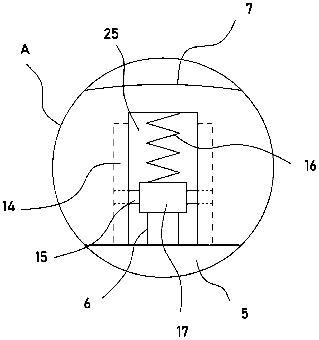
[0029] On the basis of Embodiment 1, in order to further improve the stability of the angle adjustment of the display board 5 and reduce the vibration damage to the exhibits on the display board 5, in addition, a strip groove 25 is provided in the platform 7, and the strip groove 25 The limit shaft 15 is slidingly installed inside, the limit shaft 15 is sleeved with a sleeve 17, the connecting rod 6 is fixed between the sleeve 17 and the display board 5, and the two ends of the strip groove 25 are respectively fixed on the platform. 7 and the return spring 16 on the sleeve 17, the two sides of the guide groove 14 are provided with guide grooves 14 that slide with the limit shaft 15.

[0030] When the threaded pipe 4 lifts and drives the display board 5 to adjust the angle, the limit shaft 15 slides along the guide groove 14 to guide the casing 17 during the movement process. During this period, the return spring 16 deforms to make the display board 5 adjust the angle In the pr...


PUM


Abstract

The invention discloses a display device for visual communication design, and relates to the technical field of display devices. The display device comprises a bottom plate, the bottom plate is provided with a platform, a display mechanism is mounted on the platform and comprises a plurality of circumferentially-distributed display plates, a threaded pipe is mounted at the center of the platform in a lifting mode, connecting rods slidably connected with the platform are fixed to the other ends of the display plates, and clamping mechanisms are arranged on the display plates. According to the display device, exhibits are supported through the arranged display plates, through rotating of the platform, the omni-directional display effect of circumferential rotating of the exhibits is achieved, an additionally-arranged servo motor can drive a threaded rod to rotate, height lifting of the threaded pipe is achieved, the display angles of the display plates are adjusted, the adjusting process is stable and efficient, through the arranged clamping mechanisms, the display device can adapt to the different exhibits, the great clamping and stabilizing effects are achieved, the multiple arranged display plates are used for storing and supporting the exhibits, and the display number of the exhibits displayed once is improved.

Description

technical field [0001] The invention relates to the technical field of display devices, in particular to a display device for visual communication design. Background technique [0002] Visual communication is the active behavior of disseminating specific things through visual forms, most or part of which relies on vision, and is represented by images in two-dimensional spaces such as logos, typography, paintings, graphic design, illustrations, colors, and electronic devices. In the process of visual communication design, a phenomenon has been discovered: images that communicate, educate, and persuade audiences will have greater impact when accompanied by text. [0003] The patent with the authorized notification number CN206194324U discloses a display device for visual communication design, including a base, the two ends of the upper surface of the base are respectively welded with a first shaft hole and a second shaft hole, and the first shaft hole The inner shaft of the i...

Claims


Application Information

Patent Timeline
Patent Type & Authority Applications(China)
IPC IPC(8): A47F5/025A47F5/12A47F7/00
CPCA47F5/025A47F5/12A47F7/00
Inventor 李硕胡傅强
Owner ZHONGBEI UNIV
Why Eureka
Try Eureka