Electric rotary mop

A technology of electric rotation and mop, which is applied to manual sweeping machines, carpet cleaning, floor cleaning, etc. It can solve the problems of poor cleaning effect of stubborn stains, reduce the number of times to replace the cleaning head and improve cleaning efficiency.

Inactive Publication Date: 2019-09-20
阳珉
View PDF0 Cites 2 Cited by
  • Summary
  • Abstract
  • Description
  • Claims
  • Application Information

AI Technical Summary

Problems solved by technology

[0007] The beneficial effects of the present invention mainly lie in that during the rotation of the cleaning head, the cleaning blades bent towards the direction of rotation can gradually gather the dirt and limit it to the middle position below the cleaning head, preventing the dirt from being thrown away by the rotating cleaning head; at the same time The lower edge of the cleaning blade facing the direction of rotation has a certain scraping effect on the surface to be cleaned, which can overcome the shortcomings of ordinary rotary cleaning heads that can only be wiped with the bottom plane, and the cleaning effect on stubborn stains is not good, and when the cleaning head itself is dirty , still has a certain cleaning ability, which can reduce the number of times to replace the cleaning head and improve cleaning efficiency

Method used


Image

  • Electric rotary mop
  • Electric rotary mop
  • Electric rotary mop

Examples


Embodiment 1

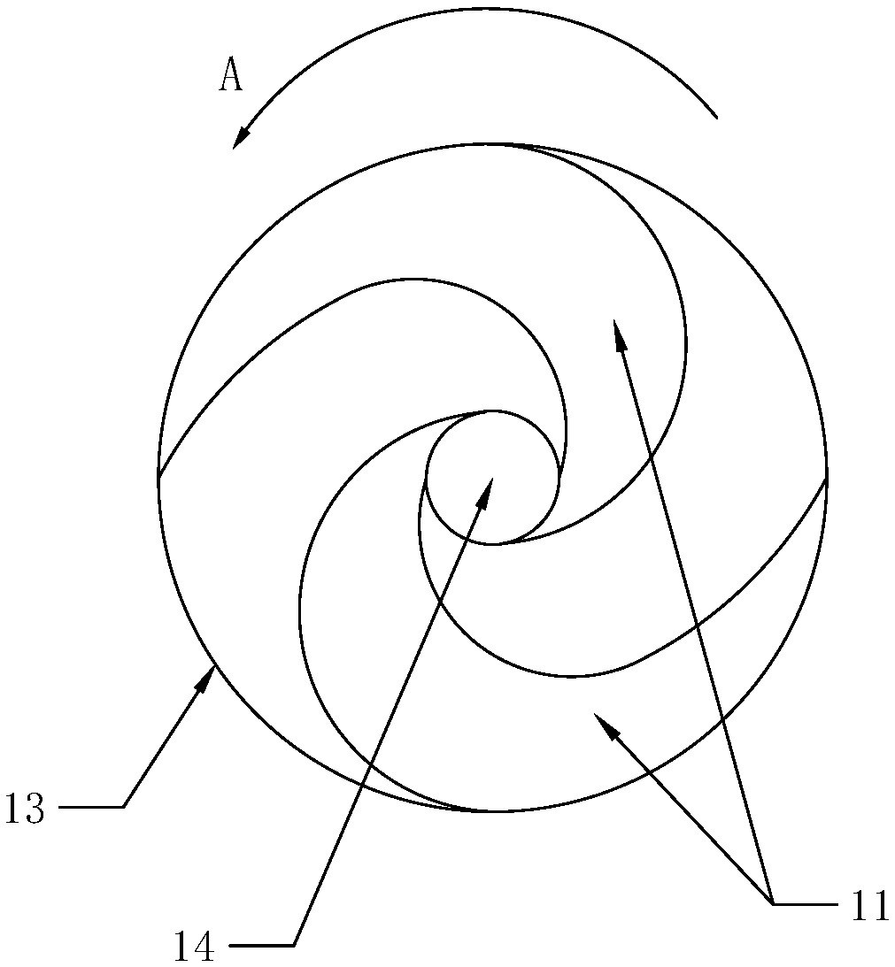
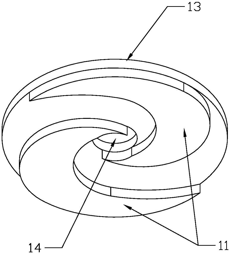
[0027] Example 1: Such as figure 1 , figure 2 As shown, the cleaning head has an impeller structure and includes two circumferentially distributed cleaning blades 11 for wiping the surface to be cleaned. In this embodiment, the direction of rotation of the cleaning head is figure 1 As shown by the middle arrow A, the cleaning blade 11 is bent toward the direction of rotation of the cleaning head; the cleaning head also includes an upper cover 13, and the cleaning blade 11 is arranged under the upper cover 13, and the center of the upper cover 13 is provided for installation positioning or dust suction The through hole 14 of the channel; in this embodiment, the material of the cleaning blade and the upper cover is a flexible absorbent wipe material, specifically preferably an integrated polyvinyl alcohol rubber cotton material, suitable for wet mopping, and can be used to clean the ground, glass, etc. Surface, and has good water absorption;

[0028] In the present invention, the i...

Embodiment 2

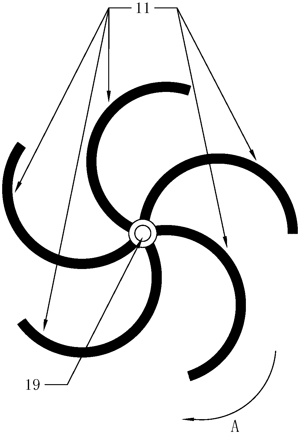
[0029] Example 2: Such as image 3 As shown, the cleaning head has an impeller structure and includes a plurality of cleaning blades 11 distributed circumferentially around the central axis 19 for cleaning the surface to be cleaned; the direction of rotation of the cleaning head is image 3 As shown by the middle arrow A, the cleaning blade 11 is bent toward the direction of rotation of the cleaning head; the cleaning blade 11 is composed of a bundle of bristles, which can be natural or artificial bristles. In order to better maintain the shape of the brush bundle, An elastic steel wire or elastic plastic strip for shaping can be arranged in the brush bundle; the cleaning head in this embodiment is mainly used as a hand-push sweeper or a sweeping robot.

Embodiment 3

[0030] Example 3: Such as Figure 4 , Figure 5 As shown, the cleaning head is an impeller structure, which is composed of a plate brush, including an upper cover 13 made of plastic, located below the upper cover, a plurality of circumferentially distributed cleaning blades 11 composed of bristles, and a central shaft of the upper cover The position is provided with a through hole 14 used as an installation location or a dust suction channel; in this embodiment, the rotation direction of the cleaning head is Figure 4 As shown by the middle arrow A, the cleaning blade 11 is bent toward the rotation direction of the cleaning head; the cleaning head in this embodiment can be used for a sweeper, a hand-push sweeper or a sweeping robot.


PUM


Abstract

The invention discloses an electric rotary mop. The electric rotary mop comprises a main machine, a push rod and a dust suction device, and further comprises two cleaning heads arranged in parallel; the cleaning heads are each of an impeller structure, and each comprise a plurality of circumferentially distributed cleaning blades for wiping and sweeping a cleaned surface; the cleaning blades are bent in the rotating direction when the cleaning heads are operated; a passage for the movement of dirt is formed between every two adjacent cleaning blades, and when the cleaning heads rotate, the cleaning blades bent in the rotation direction can enable the dirt to perform centered movement along the rotating sides of the cleaning blades, so that the role of collecting the dirt is achieved; and the cleaning heads can effectively overcome the disadvantage that ordinary rotary cleaning tools cannot collect the dirt and are prone to throwing off the dirt, and the cleaning efficiency is improved.

Description

Technical field [0001] The invention relates to the field of cleaning tools, in particular to an electric rotating mop. Background technique [0002] In the prior art, tools for cleaning by rotating the cleaning head have been widely used, such as sweepers, mopping machines, electric rotary mops, sweeping robots, electric window cleaners, etc. The cleaning heads generally use disc brushes, circular Mop, or side brush and other structures. [0003] Take a common electric rotating mop as an example. Its cleaning head usually uses one or two round mops, which are driven to rotate by a motor installed in the body to wipe the ground. However, because the available area of ​​the mop is limited, it can only be rubbed by rotation. It can’t pack the dirt together like an ordinary mop, so the mop is very easy to get dirty. If you drag a small piece of ground, you must take off the mop for replacement and cleaning, even more often than ordinary hand-push mops. Increase a lot; in addition, b...

Claims


Application Information

Patent Timeline
Patent Type & Authority Applications(China)
IPC IPC(8): A47L11/24A47L11/40
CPCA47L11/24A47L11/40A47L11/4038A47L11/4094
Inventor 阳珉
Owner 阳珉
Why Eureka
Try Eureka