Circumferential acceleration type material issuing chamber for horizontal screw centrifugal machine

A decanter centrifuge and material technology, which is applied in the field of centrifuges, can solve the problems of low feed circumferential speed and low material separation efficiency in the separation liquid tank, so as to reduce liquid slippage, reduce circumferential speed difference, and improve separation efficiency effect

Pending Publication Date: 2019-09-20
ZHEJIANG UNIV OF TECH
View PDF0 Cites 0 Cited by
  • Summary
  • Abstract
  • Description
  • Claims
  • Application Information

AI Technical Summary

Problems solved by technology

[0003] In order to solve the problem of low feeding circumferential speed and low material separation efficiency in the separation liquid tank in the prior art, the present invention provides a circumferentially accelerated material distribution chamber for a decanter centrifuge

Method used


Image

  • Circumferential acceleration type material issuing chamber for horizontal screw centrifugal machine
  • Circumferential acceleration type material issuing chamber for horizontal screw centrifugal machine
  • Circumferential acceleration type material issuing chamber for horizontal screw centrifugal machine

Examples


Embodiment Construction

[0029] The technical solution of the patent of the present invention will be clearly and completely described below in conjunction with the accompanying drawings. Apparently, the described embodiments are part of the embodiments of the present invention, not all of them. Based on the embodiments of the present invention, all other embodiments obtained by persons of ordinary skill in the art without making creative efforts belong to the protection scope of the present invention.

[0030] In the description of the present invention, it should be noted that if the terms "center", "upper", "lower", "left", "right", "vertical", "horizontal", "inner", "outer" appear ” and other indicated orientations or positional relationships are based on the orientations or positional relationships shown in the accompanying drawings, which are only for the convenience of describing the present invention and simplifying the description, rather than indicating or implying that the referred device or...


PUM


Abstract

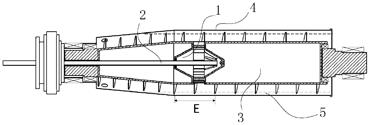
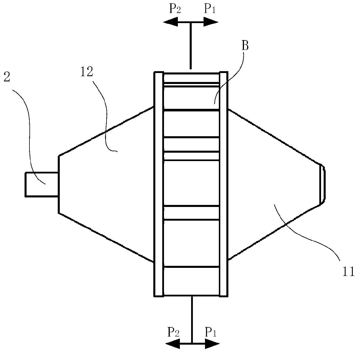
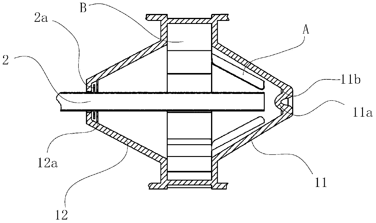
The invention discloses a circumferential acceleration type material issuing chamber for a horizontal screw centrifugal machine. The circumferential acceleration type material issuing chamber for the horizontal screw centrifugal machine is characterized in that a material issuing chamber body is fixedly arranged in a hollow shaft of a spiral conveyor and rotates along with a spiral conveying shaft; the material issuing chamber comprises a first conical cavity, first-stage blades, a second conical cavity and second-stage blades, wherein the small end face of the first conical cavity is of a convex circular structure, the convex circle of the small end face of the first conical cavity faces an outlet of the feeding pipe, the first-stage blades are uniformly welded on the conical surface of the first conical cavity in the circumferential direction, inlet edges of the first-stage blades are flush with the outlet plane of the feeding pipe, and outlet edges of the first-stage blades are flush with the large end face of the first conical cavity; the large end face of the second conical cavity faces the large end face of the first conical cavity, the feeding pipe penetrates through the center of the small end face of the second conical cavity, the second-stage blades are uniformly welded between the large end face of the first conical cavity and the large end face of the second conical cavity in the circumferential direction, and the first conical cavity, the first-stage blades, the second conical cavity, the second-stage blades coincide with the axis of the feeding pipe. According to the circumferential acceleration type material issuing chamber, the separation efficiency of the horizontal screw centrifuge is improved.

Description

technical field [0001] The invention belongs to the field of centrifuges, and in particular relates to a circumferentially accelerating material distribution chamber for a decanter centrifuge. Background technique [0002] Considering the particularity of axial feeding and double rotor structure, the decanter centrifuge needs to set a material distribution chamber in the inner cavity of the screw conveying shaft as a transition zone between the material from the feed pipe to the drum separation chamber. Most of the material distribution chambers of decanter centrifuges on the market are simple cylindrical chambers with discharge holes. The process of the material to be separated entering the rotating material distribution chamber from the stationary feed pipe is mostly concentrated flow or jet flow, and The transition without flow guide device leads to the disordered flow of materials in the material distribution chamber, which not only wastes most of the energy required for...

Claims


Application Information

Patent Timeline
Patent Type & Authority Applications(China)
IPC IPC(8): B04B1/20B04B7/00B04B11/06
CPCB04B1/20B04B7/00B04B11/06B04B2001/2033
Inventor 周水清周华欣李曰兵高增梁周凌峰
Owner ZHEJIANG UNIV OF TECH
Why Eureka
Try Eureka