Charging pile system of new energy vehicle

A new energy vehicle and charging pile system technology, applied in the field of new energy vehicle charging pile system, can solve the problems that charging piles cannot be used effectively, new energy vehicles cannot be charged, etc.

Active Publication Date: 2019-09-20
郑州叮叮智能科技有限公司
View PDF10 Cites 3 Cited by
  • Summary
  • Abstract
  • Description
  • Claims
  • Application Information

AI Technical Summary

Problems solved by technology

[0004] In view of this, the purpose of the present invention is to provide a new energy vehicle charging pile system for the deficiencies of the prior art, by setting four wheel assists for carrying and moving the four wheels of the new energy v

Method used


Image

  • Charging pile system of new energy vehicle
  • Charging pile system of new energy vehicle
  • Charging pile system of new energy vehicle

Examples


Embodiment 1

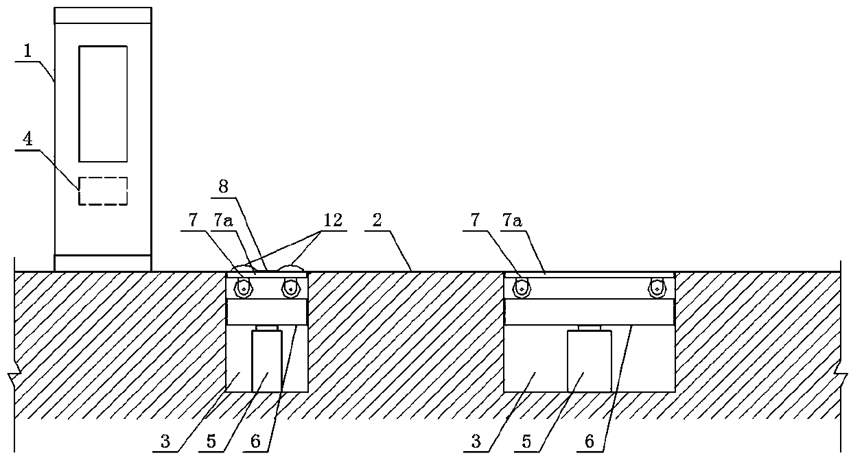
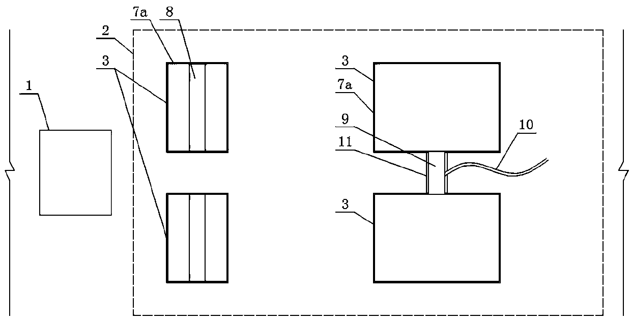
[0044] Such as figure 1 and figure 2 As shown, a new energy vehicle charging pile system includes a charging pile body 1, and the ground position in front of the charging pile body 1 is set as a parking area 2, and the parking area 2 is provided with four rectangular foundation pits 3. The positions of the four foundation pits 3 correspond to the positions of the four wheels of the new energy vehicle, and each foundation pit 3 is provided with a wheel auxiliary mechanism, which is used for carrying, moving and assisting the wheels. The position of the mechanism corresponds to the wheel of the new energy vehicle, and the opening and closing of the wheel auxiliary mechanism is controlled by the PLC controller 4 of the charging pile body 1 .

[0045] The wheel auxiliary mechanism includes an automatic telescopic cylinder 5 vertically arranged in the foundation pit 3, a rectangular bearing plate 6 is arranged on the top of the automatic telescopic cylinder 5, and a flat trolley ...

Embodiment 2

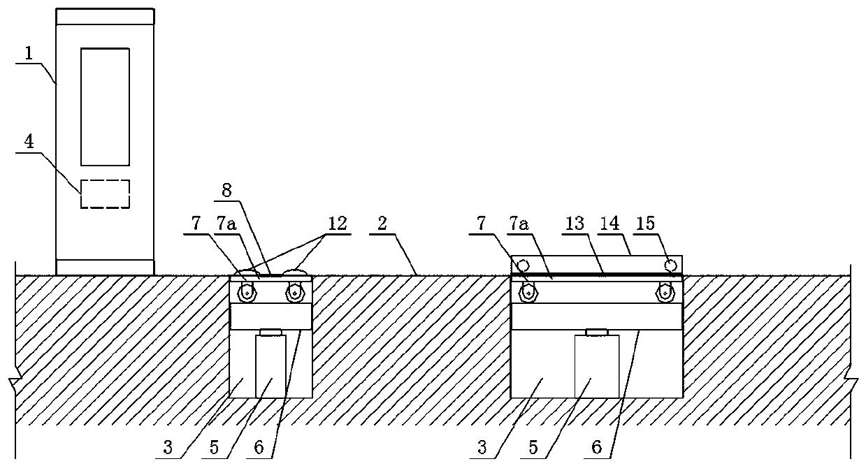
[0053] Such as image 3 and Figure 4 As shown, the difference from Embodiment 1 is that the flat trolley 7 of the two wheel auxiliary mechanisms far away from the charging pile body 1 is longer than the flat trolley of the two wheel auxiliary mechanisms close to the charging pile body 1 7, and the outer side of the flatbed trolley 7 of the two wheel auxiliary mechanisms far away from the charging pile body 1 is equipped with a tightening mechanism, which is used for tightening and temporarily fixing the new energy vehicle Wheels; the tightening mechanism includes a horizontal extension plate 13 arranged on the outside of the flat trolley 7 car plate 7a away from the charging pile body 1, the outer end of the extension plate 13 is provided with a vertical plate 14, and the inner side of the vertical plate 14 A tightening plate 16 is provided through the automatic telescopic rod 15, and the tightening plate 16 is used to tighten the outer surface of the wheel of the new energy...

Embodiment 3

[0059] Such as Figure 5 and Figure 6 As shown, the difference between it and the second embodiment is that the four sides of the bearing plate 6 are connected with the inner side of the corresponding foundation pit 3 through a slide rail chute structure that can slide relative to each other in the vertical direction, and the slide rail The chute structure includes slide rails 17 arranged on the four inner sides of the foundation pit 3, and the side surfaces of the bearing plate 6 and the side surfaces of the flat trolley 7 vehicle plate 7a are all provided with sliding rails 17 that cooperate with the slide rails 17. The chute 18.

[0060] In this embodiment, in order to ensure that the flat trolley and the bearing plate can slide vertically relative to the foundation pit smoothly, and at the same time provide the lateral support force for the flat trolley when carrying the wheels of new energy vehicles, avoid The offset causes the flat trolley to tilt, and the four sides of...


PUM


Abstract

The invention discloses a charging pile system of a new energy vehicle. The charging pile system comprises a charging pile body, wherein a parking region is arranged on a ground position in front of the charging pile body; four rectangular foundation pits are formed in the parking region; the positions of the four foundation pits correspond to those of four wheels of the new energy vehicle; a wheel assisting mechanism is arranged in each foundation pit, and the wheel assisting mechanism is used for bearing and moving the wheel, which is on the position of the wheel assisting mechanism, of the new energy vehicle, and the wheel assisting mechanism is controlled to start and stop by a PLC of the charging pile body. According to the charging pile system disclosed by the invention, the wheel assisting mechanisms for bearing and moving the four wheels of the new energy vehicle are separately arranged on the parking region, so that the problems that other new energy vehicles needing charging cannot be charged as the parking region is occupied, and the charging pile cannot be effectively used are radically solved.

Description

technical field [0001] The invention belongs to the technical field of charging pile design, in particular to a new energy vehicle charging pile system. Background technique [0002] As people pay more and more attention to green and environmental protection, electric vehicles (also called new energy vehicles) have become an industry strongly supported by the state because of their cleanliness and environmental protection. The charging piles supporting new energy vehicles have also developed rapidly accordingly. However, since the construction of charging piles requires not only power supply and funds, but also land and local property support, this has far exceeded the scope that enterprises such as power grids can solve by themselves. Therefore, the current number of charging piles is very limited. It is even more regrettable that in the current situation where the number of charging piles is seriously insufficient, charging piles are still occupied by vehicles without ch...

Claims


Application Information

Patent Timeline
IPC IPC(8): B60L53/31B60L53/65E01F13/04
CPCB60L53/31B60L53/65E01F13/046Y02T10/70Y02T10/7072Y02T90/12
Inventor 丁锐
Owner 郑州叮叮智能科技有限公司
Why Eureka
Try Eureka