A new energy vehicle charging pile system
A new energy vehicle and charging pile system technology, applied in the field of new energy vehicle charging pile systems, can solve problems such as the inability to charge new energy vehicles and the ineffective use of charging piles.
- Summary
- Abstract
- Description
- Claims
- Application Information
AI Technical Summary
Problems solved by technology
Method used
Image
Examples
Embodiment 1
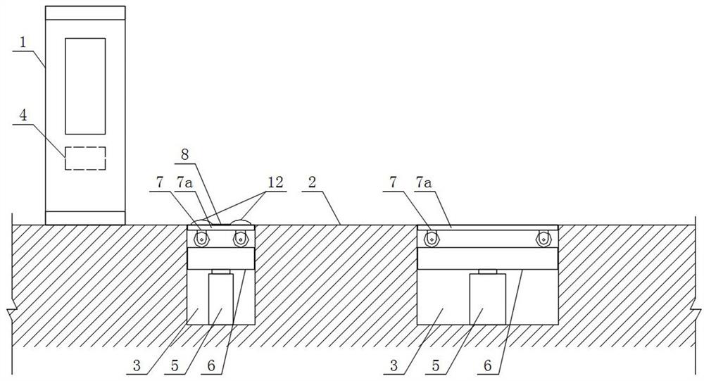
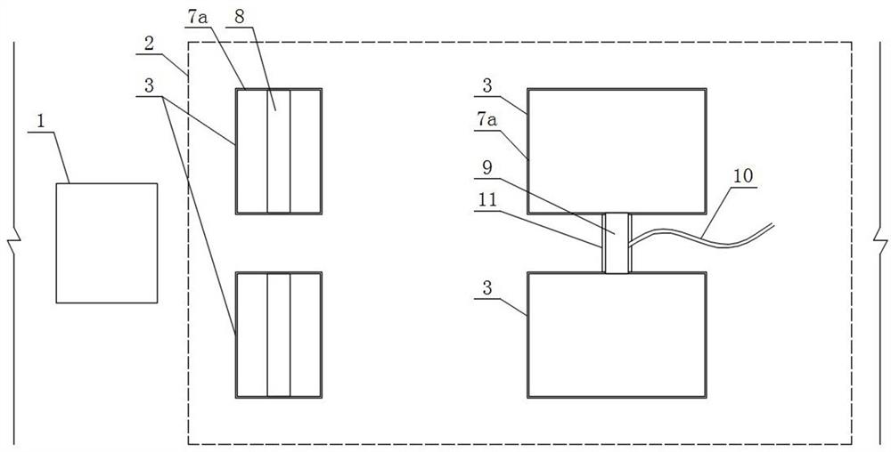
[0044] like figure 1 and figure 2 As shown, a new energy vehicle charging pile system includes a charging pile body 1, and the ground position in front of the charging pile body 1 is set as a parking area 2, and the parking area 2 is provided with four rectangular foundation pits 3. The positions of the four foundation pits 3 correspond to the positions of the four wheels of the new energy vehicle. Each foundation pit 3 is provided with a wheel auxiliary mechanism, and the wheel auxiliary mechanism is used to carry, move and assist the wheel. The position of the mechanism corresponds to the wheel of the new energy vehicle, and the opening and closing of the wheel auxiliary mechanism is controlled by the PLC controller 4 of the charging pile body 1 .
[0045] The wheel auxiliary mechanism includes an automatic telescopic cylinder 5 vertically arranged in the foundation pit 3. A rectangular carrying plate 6 is arranged on the top of the automatic telescopic cylinder 5, and a f...
Embodiment 2
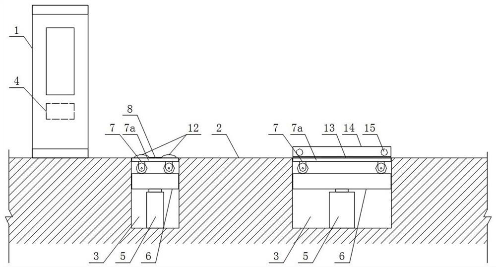
[0053] like image 3 and Figure 4 As shown in the figure, the difference from the first embodiment is that the length of the flatbed trolley 7 with the two wheel auxiliary mechanisms far from the charging pile body 1 is longer than that of the flatbed trolley with the two wheel auxiliary mechanisms close to the charging pile body 1 7 length, and the outer side of the deck 7a of the flatbed trolley 7 of the two wheel auxiliary mechanisms that are far from the position of the charging pile body 1 is provided with a jacking mechanism, which is used to jack up and temporarily fix the new energy vehicle. Wheels; the jacking mechanism includes a horizontal extension plate 13 arranged on the outer side of the deck 7a of the flatbed trolley 7 at a position away from the charging pile body 1, the outer end of the extension plate 13 is provided with a vertical plate 14, and the inner side of the vertical plate 14 The automatic telescopic rod 15 is provided with a pressing plate 16 for...
Embodiment 3
[0059] like Figure 5 and Image 6 As shown, the difference between it and the second embodiment is that the four sides of the bearing plate 6 and the inner side of the corresponding foundation pit 3 are connected by a sliding rail and chute structure that can slide relative to each other in the vertical direction. The chute structure includes slide rails 17 arranged on the four inner sides of the foundation pit 3 , and the side surfaces of the carrying plate 6 and the side surfaces of the pallet 7 a of the pallet 7 are provided with the slide rails 17 to match. the chute 18.
[0060] In this embodiment, in order to ensure that the flatbed trolley and the carrying plate can smoothly slide relative to the foundation pit in the vertical direction, and at the same time, it can provide lateral support for the flatbed trolley when carrying the wheels of the new energy vehicle, so as to avoid the problems caused by the parking position of the new energy vehicle. The offset causes th...
PUM
 Abstract
Description
Claims
Application Information
 - R&D
- Intellectual Property
- Life Sciences
- Materials
- Tech Scout
- Unparalleled Data Quality
- Higher Quality Content
- 60% Fewer Hallucinations
Browse by: Latest US Patents, China's latest patents, Technical Efficacy Thesaurus, Application Domain, Technology Topic, Popular Technical Reports.
© 2025 PatSnap. All rights reserved.Legal|Privacy policy|Modern Slavery Act Transparency Statement|Sitemap|About US| Contact US: help@patsnap.com


