Supercharge Your Innovation With Domain-Expert AI Agents!

Seawater desalination device suitable for offshore floating platform

A floating platform and seawater technology, applied in seawater treatment, water/sewage treatment, general water supply conservation, etc., can solve problems such as large energy consumption, and achieve the effect of solving the problem of low water yield

Pending Publication Date: 2019-09-20
JIANGSU UNIV OF SCI & TECH
View PDF5 Cites 7 Cited by
  • Summary
  • Abstract
  • Description
  • Claims
  • Application Information

AI Technical Summary

Problems solved by technology

However, the above-mentioned seawater desalination needs to consume a large amount of energy

Method used


Image

  • Seawater desalination device suitable for offshore floating platform
  • Seawater desalination device suitable for offshore floating platform
  • Seawater desalination device suitable for offshore floating platform

Examples


Embodiment 1

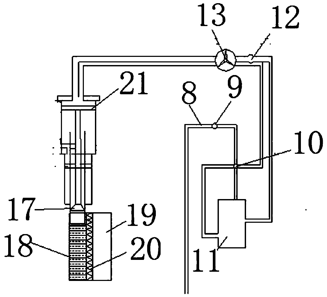
[0031] Such as figure 1 As shown, a seawater desalination device suitable for offshore floating platforms includes a wave energy energy unit and a seawater desalination system. The seawater desalination system includes a seawater tank 18, a piston, a fresh water tank 19, and a semi-permeable membrane 20. The permeable membrane 20 is between the sea water tank 18 and the fresh water tank 19, the bottom end of the piston is in contact with the sea water in the sea water tank, the sea water desalination system is also provided with an oil tank 11, and the wave energy energy unit stores gas The compressed air in tank 1 enters the oil tank 11 through the No. 1 power input pipe 8. The hydraulic oil squeezed from the oil tank 11 squeezes the piston through the oil inlet pipe, and the hydraulic oil passes through the oil return pipe through the pneumatic machine 10 To the fuel tank 11.

[0032] A first power valve 9 is provided between the No. 1 power input pipe 8 and the oil tank 11.

[...

Embodiment 2

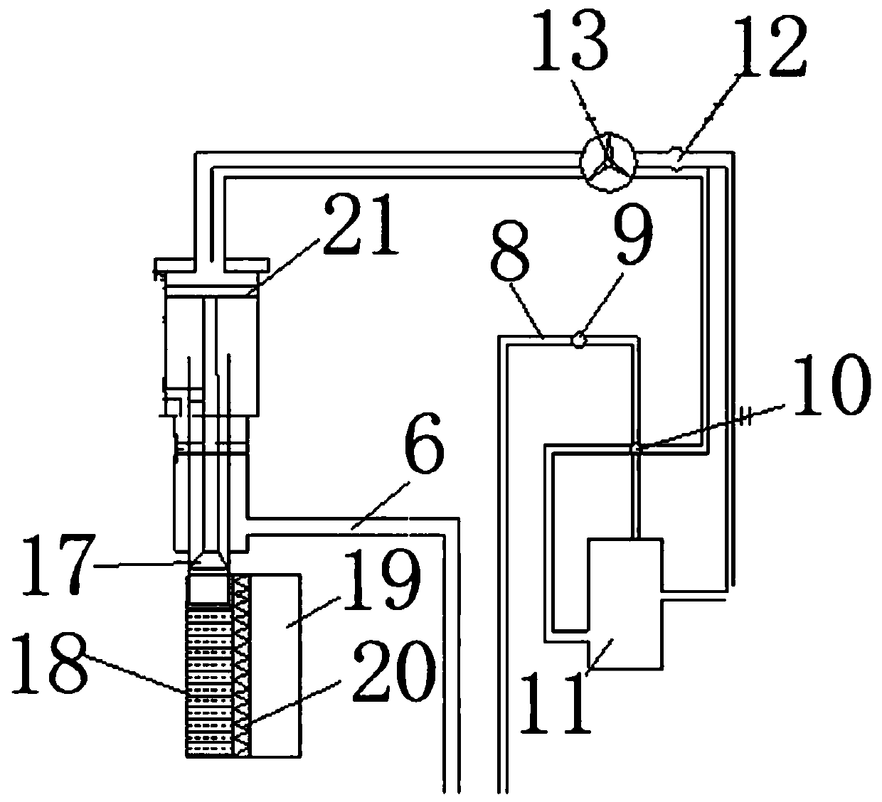
[0036] Such as figure 2 As shown, as the depth of the piston squeezing the seawater increases, the required energy gradually increases. On the basis of Example 1, a power input pipe, namely the second power input pipe 6, is added, and the piston is divided into two layers. , Respectively, the upper piston 21 and the lower piston 17. When the upper piston 31 is squeezed, the compressed air in the air tank 1 of the wave energy energy unit squeezes the lower piston 17 through the second power input pipe 6 .

Embodiment 3

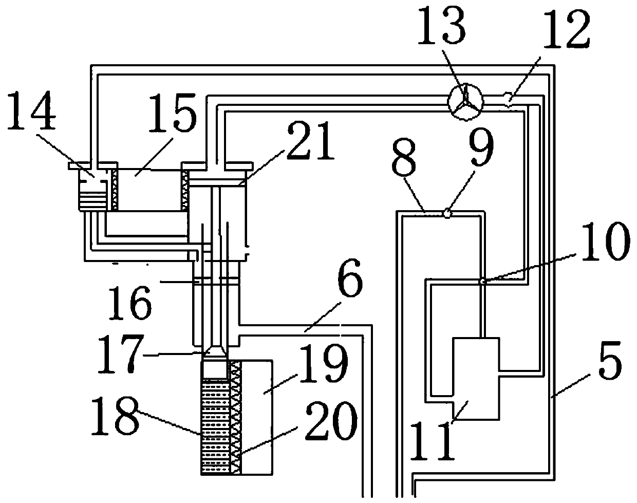
[0038] Such as image 3 As shown, on the basis of Example 2, in order to better squeeze the piston, a layer of middle piston 16 is added to the piston. The middle piston 16 is located between the upper piston 21 and the lower piston 17, and one more power is added. The input pipe is the No. 3 power input pipe 5. The compressed air in the air storage tank 1 of the wave energy energy unit squeezes the component oil tank 14 so that the hydraulic oil of the component oil tank 14 squeezes the middle piston 17.


PUM


Abstract

The invention provides a seawater desalination device suitable for an offshore floating platform. The seawater desalination system comprises a seawater tank, a fresh water tank and a semipermeable membrane; the semipermeable membrane is arranged between the seawater tank and the fresh water tank; the bottom end of the piston makes contact with seawater in the seawater tank. An oil tank is arranged in the sea water desalination system, compressed air in an air storage tank of the wave energy unit enters the oil tank through a first power input pipe, and hydraulic oil in the oil tank is extruded to extrude a piston through an oil inlet pipeline and then returns to the oil tank through an oil return pipeline by a pneumatic machine. According to the invention, wave energy is used for pushing the suspended simple pendulum to move, converting the wave energy into mechanical energy, compressing air through the pneumatic machine, pressing hydraulic oil in the oil tank and pushing the piston to move, and the piston forces seawater to pass through the semipermeable membrane, so that salt and other impurities in the seawater are separated from fresh water. Power of the device comes from wave energy and is large, and therefore the technical problem that seawater is large in energy consumption is solved.

Description

Technical field [0001] The invention relates to a seawater desalination device, in particular to a seawater desalination device suitable for marine floating platforms. Background technique [0002] Water is a basic natural resource, and water resources are an important guarantee for the sustainable development of the national economy and society. Today, the shortage of freshwater resources has become a global problem, and the current situation is not optimistic. my country is a country with drought and water shortage. The per capita freshwater resources are only 2,200 cubic meters. The water resources in the northern coastal areas and islands are more serious. With the increasing depletion of traditional fossil fuels, various new energy technologies are developing rapidly. It is possible to combine new renewable energy technology with seawater desalination equipment. Desalination of seawater using renewable energy is one of the fundamental measures to solve the shortage of wat...

Claims


Application Information

Patent Timeline
IPC IPC(8): C02F1/44C02F103/08
CPCC02F1/44C02F2103/08C02F2201/001C02F2303/10Y02A20/131
Inventor 沈中祥王文庆尹群朱贤杰
Owner JIANGSU UNIV OF SCI & TECH
Features
  • R&D
  • Intellectual Property
  • Life Sciences
  • Materials
  • Tech Scout
  • Unparalleled Data Quality
  • Higher Quality Content
  • 60% Fewer Hallucinations
Learn More