
Scaffold supporting structure and system

A technology for supporting structure and supporting system, which is applied in the direction of housing structure support, housing structure support, scaffolding accessories, etc. It can solve the problems of limited application scope, unclear force on the structural system, hidden dangers of safety and quality, etc., and achieve fast installation and disassembly. Simple, saves the overall erection time, and has the effect of reliable support

Active Publication Date: 2019-09-20
东莞市建筑科学研究院有限公司
View PDF6 Cites 3 Cited by
  • Summary
  • Abstract
  • Description
  • Claims
  • Application Information

AI Technical Summary

Problems solved by technology

However, the installation and construction of cantilevered scaffolding involves reservation and pre-embedding, opening and filling holes, open flame welding and multi-component installation in terms of construction procedures. The workload is large, the construction is troublesome, and there are certain hidden safety and quality problems ; From the perspective of applicable position, traditional cantilevered I-beams and steel wire ropes cannot be installed at positions with bay windows, and the scope of application is limited; From the perspective of structural force, the force transmission path in the conventional calculation model of cantilevered scaffolding is the external scaffolding The upper load is transferred to the I-beam main girder by hoisting and unloading with multiple steel wire ropes, and finally carried by the main structure of the building. There are certain disputes about related calculations, that is, whether steel wire ropes can participate in the load calculation, industry norms (JGJ130-2011) Relevant provisions indicate that the steel wire rope does not participate in the force calculation of the cantilevered steel beam, that is, the steel wire rope is regarded as a safety reserve, and considering that it may be in a relaxed state, only when the steel wire rope is tightened can it really participate in the unloading of the structure. clear question

Method used


Image

  • Scaffold supporting structure and system
  • Scaffold supporting structure and system
  • Scaffold supporting structure and system

Examples


specific Embodiment approach

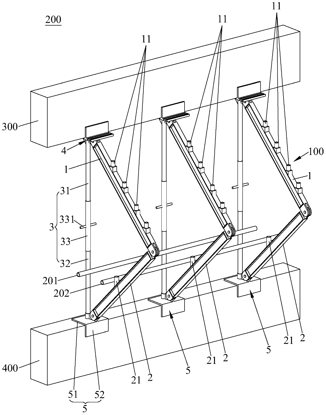
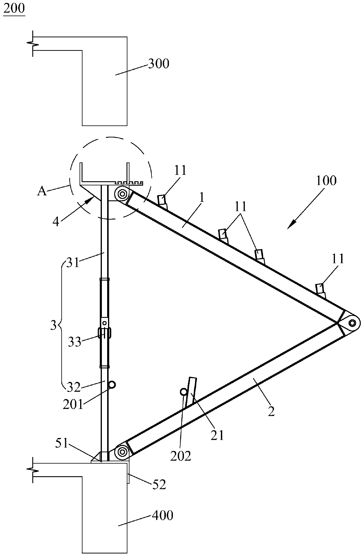
[0027] combine figure 2 and Figure 4 , taking the three scaffolding support structure 100 as an example, the specific implementation of the scaffolding support system 200 of the present invention is as follows:

[0028] S1, process and manufacture all parts of the present invention, weld the support 11 at the preset position of the first diagonal support 1, weld the auxiliary rod at the preset position of the second diagonal support 2, and transport the manufactured parts to Construction and installation floors;

[0029] S2, place the components on a simple flatbed truck for plane installation, forming a figure 1 For the scaffold support structure 100 shown, the simple flatbed truck is moved to the installation position, the scaffold support structure 100 is suspended by a tower crane, and the second engaging part 5 is engaged on the lower side beam 400;

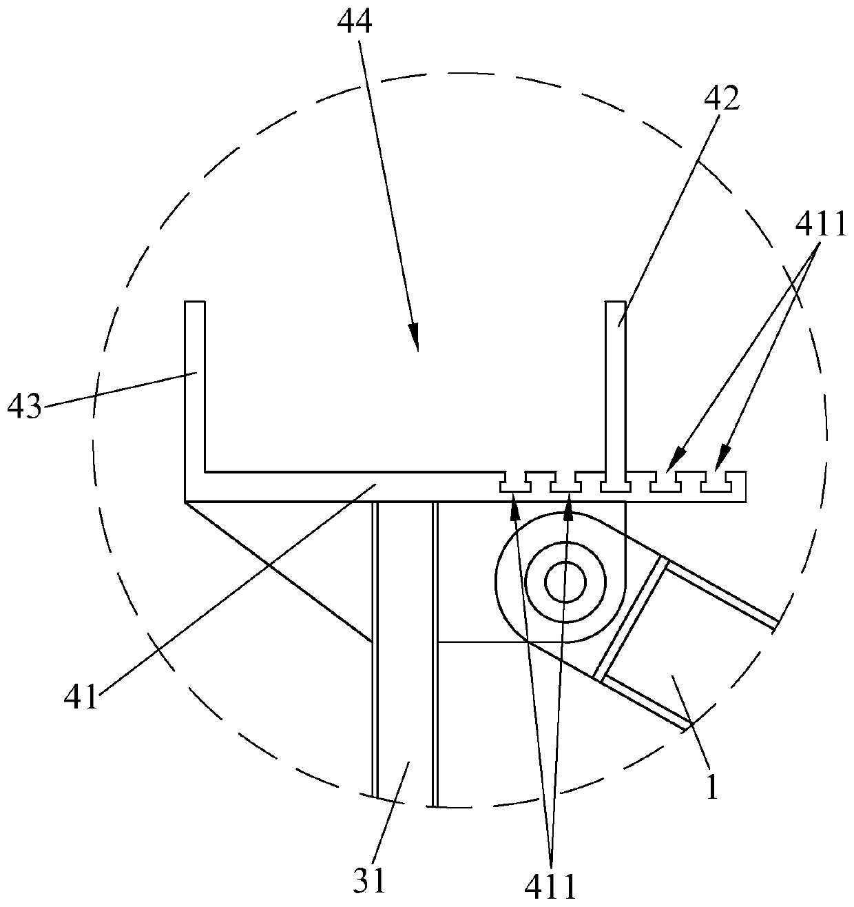
[0030] S3, adjust the first side plate 42 into a suitable adjustment groove 411 according to the beam width of the up...


PUM


Abstract

The invention provides a scaffold supporting structure and system, and relates to the field of building tools. The scaffold supporting structure comprises a first inclined supporting part, a second inclined supporting part and a lifting assembly, a support allowing a scaffold to be mounted is arranged on the first inclined supporting part, the first end of the first inclined supporting part is in pivot joint with the first end of the second inclined supporting part, a first clamping part is arranged at the first end of the lifting assembly, a second clamping part is arranged at the second end of the lifting assembly, the second end of the first inclined supporting part is in pivot joint with the first clamping part, and the second end of the second inclined supporting part in pivot joint with the second clamping part; and the lifting assembly drives the first clamping part and the second clamping part to move, so that the first clamping part is clamped on an upper layer edge beam, and the second clamping part is clamped on a lower layer edge seam. The scaffold supporting structure is rapid, easy and convenient to mount and demount, work such as reserving, pre-burying, hole opening and filling, steel wire rope oblique-pulling and open fire welding is omitted, and the overall erecting time of the cantilevered scaffold is saved.

Description

technical field [0001] The invention relates to the field of construction tools, in particular to a scaffold support structure and a scaffold support system. Background technique [0002] In the special construction of high-rise buildings, cantilevered scaffolding is often used for external wall masonry, external facade decoration, and reinforced concrete engineering. By pre-embedding the compression ring reinforcement on the floor and penetrating the I-shaped steel beam, with several wire ropes or The steel tie rods are unloaded, and then the scaffolding rods are installed, and finally the conventional cantilevered external scaffolding project is completed. After years of practice, a mature process has been developed. However, the installation and construction of cantilevered scaffolding involves reservation and pre-embedding, opening and filling holes, open flame welding, and multi-component installation in terms of construction procedures. The workload is large, the const...

Claims


Application Information

Patent Timeline
IPC IPC(8): E04G3/18E04G5/00E04G5/04
CPCE04G3/18E04G5/00E04G5/04
Inventor 张彤炜麦镇东周书东刘亮张益叶雄明郑大叶黄志明徐伟峰黄剑
Owner 东莞市建筑科学研究院有限公司
Learn More