Supercharge Your Innovation With Domain-Expert AI Agents!

High pressure difference multi-stage pressure reducing regulating ball valve

A high-pressure differential and regulating ball technology, which is applied in the field of regulating valves, can solve problems such as inability to solve high-pressure differential working condition adaptability, poor working condition adaptability, and difficult processing, and achieve convenient processing, improved decompression and noise reduction, and reduced Effect of Difficulty of Maintenance

Active Publication Date: 2021-02-09
HEFEI GENERAL MACHINERY RES INST
View PDF11 Cites 0 Cited by
  • Summary
  • Abstract
  • Description
  • Claims
  • Application Information

AI Technical Summary

Problems solved by technology

[0003] There are many restrictions on the direct use of ball valves with ordinary structures as regulating valves, for example: it should be avoided to be used under the condition of small opening; it cannot be used in high pressure differential conditions, etc.
Even for the V-type regulating ball valve, which has a high adjustable ratio and can adapt to media containing fibers, tiny solid particles, slurry, etc., it still cannot solve the problem of adaptability to high pressure differential conditions
[0004] In order to deal with the adaptability of the regulating ball valve under the condition of high pressure difference, technicians in the industry have proposed various technical solutions, but the multi-stage pressure-reducing / noise-reducing regulating ball valve in the prior art is still generally difficult to process and difficult to maintain , poor adaptability to working conditions, etc.

Method used


Image

  • High pressure difference multi-stage pressure reducing regulating ball valve
  • High pressure difference multi-stage pressure reducing regulating ball valve
  • High pressure difference multi-stage pressure reducing regulating ball valve

Examples


Embodiment Construction

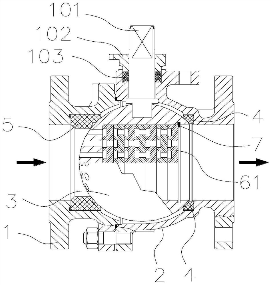
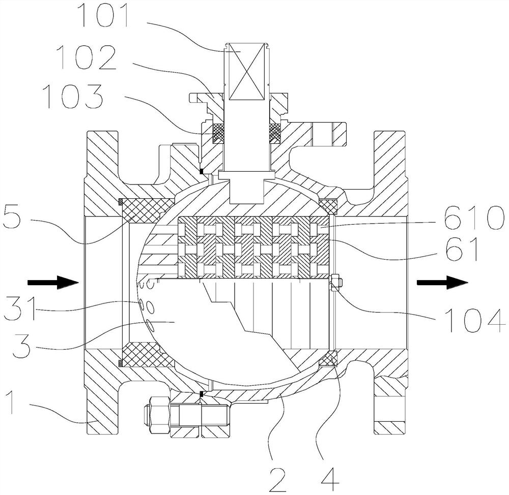
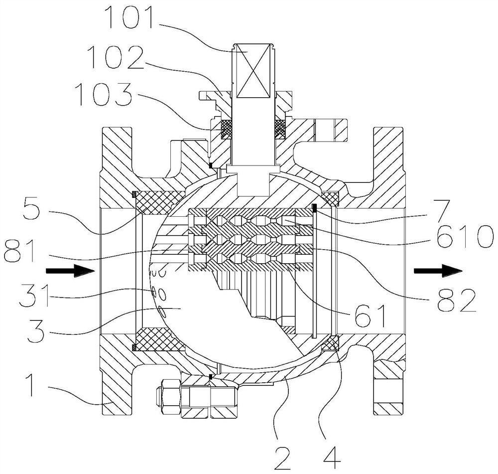
[0049] Such as Figure 1-12 As shown, the high-pressure differential multi-stage pressure-reducing regulating ball valve includes a valve body, a ball 3, and a valve stem 101. The valve body can be top-mounted or two-piece or three-piece, and the ball 3 can be a fixed ball or It's a floating ball. In this embodiment, the valve body is a two-piece type, consisting of a left valve body 1 and a right valve body 2 respectively. The ball 3 is arranged in the valve body. The top of the sphere 3 is connected with the valve stem 101, and the sphere 3 is driven to rotate by the rotation of the valve stem 101. The left and right sides of the valve body are respectively provided with an inlet valve seat 5 and an outlet valve seat 4. The ball 3 is also provided with a notch 33 interconnected with the valve stem 101, and the notch 33 can be a square groove, a flat groove or a spline groove. The valve stem 101 can be sealed with graphite packing 103 or PTFE packing 103 or an O-ring seal,...


PUM


Abstract

High pressure difference multi-stage decompression regulating ball valve, the ball valve includes a valve body, a ball, a valve stem, the ball is set in the valve body, the left and right sides of the valve body are respectively provided with an inlet valve seat and an outlet valve seat, and a cavity is opened on one side of the ball A replaceable throttling assembly is arranged in the cavity, and a plurality of groups of through holes penetrating the sphere are arranged on the inner wall in the length direction of the cavity. The throttling assembly includes a plurality of independent channels, each independent channel and each group of through holes form an independent fluid channel, the fluid channel is divided into several sections, and along the direction of fluid flow, the minimum cross-sectional area of ​​the fluid channel in adjacent sections gradually changes Large or unchanged. The invention can realize multi-stage decompression and noise reduction through the throttling assembly arranged in the cavity, and the throttling assembly can be replaced, which can be applied to different working conditions and reduces the difficulty of maintenance. The setting of independent fluid channels can adapt to high pressure Under the condition of poor working conditions, the precise adjustment of flow / pressure can be realized.

Description

technical field [0001] The invention relates to the technical field of regulating valves, in particular to a high-pressure differential multi-stage decompression regulating ball valve. Background technique [0002] Ball valves are widely used in long-distance pipelines, electric power, water conservancy and other industries, and occupy a pivotal position in the national economy. The ball valve is mainly used to cut off, distribute and change the flow direction of the medium in the pipeline. It only needs to be rotated 90 degrees and a small rotational torque can be closed tightly. Ball valves are most suitable for on-off and shut-off valves, but in recent years more and more ball valves have been used for regulating purposes. [0003] There are many restrictions on the direct use of ball valves with ordinary structures as regulating valves, for example: it should be avoided to be used under the condition of small opening; it cannot be used in high pressure differential cond...

Claims


Application Information

Patent Timeline
Patent Type & Authority Patents(China)
IPC IPC(8): F16K5/06F16K5/08F16K47/04
CPCF16K5/0605F16K5/08F16K47/045Y02B30/70
Inventor 陈凤官王渭明友耿圣陶余宏兵叶晓节王勤杨玲玲靳卫华
Owner HEFEI GENERAL MACHINERY RES INST
Features
  • R&D
  • Intellectual Property
  • Life Sciences
  • Materials
  • Tech Scout
  • Unparalleled Data Quality
  • Higher Quality Content
  • 60% Fewer Hallucinations
Learn More