
RFID (radio frequency identification) tag and screw loosening state monitoring system based on same

A technology of RFID tags and screws, which is applied in the field of screw status monitoring, can solve problems such as screw error detection status, screw missed detection or false detection, screw missed detection, etc., and achieve the effect of improving reliability

Inactive Publication Date: 2019-09-20
UNIV OF ELECTRONICS SCI & TECH OF CHINA
View PDF11 Cites 3 Cited by
  • Summary
  • Abstract
  • Description
  • Claims
  • Application Information

AI Technical Summary

Problems solved by technology

The RFID tag structure is divided into two parts, wherein the first part includes a first coupling circuit; the second part includes a second coupling circuit; when the screw is tightened, the first coupling circuit communicates with the second coupling circuit, indicating that the RFID tag is valid; When the screw is loose, the first coupling circuit and the second coupling circuit are disconnected, and the RFID tag is invalid; however, this detection method may miss or misdetect the screw; the details are as follows:
[0007] 1) When the screw is loose, according to its disclosed implementation, the two parts through which the screw rod passes may not be separated. At this time, the tag can continue to communicate with the reader normally, and the screw is still detected as a tightened state , there is a problem of missed detection of screws;
[0008] 2) When the tag is in use, the coupling circuit fixed on the two components is offset, etc. At this time, the tag cannot communicate with the reader normally, and the screw is detected as loose, and the screw will have an error detection state at this time
Therefore, the technical solution disclosed in the patent has the problem of screw misdetection

Method used


Image

  • RFID (radio frequency identification) tag and screw loosening state monitoring system based on same
  • RFID (radio frequency identification) tag and screw loosening state monitoring system based on same
  • RFID (radio frequency identification) tag and screw loosening state monitoring system based on same

Examples


Embodiment Construction

[0024] In order to facilitate those skilled in the art to understand the technical content of the present invention, the content of the present invention will be further explained below in conjunction with the accompanying drawings.

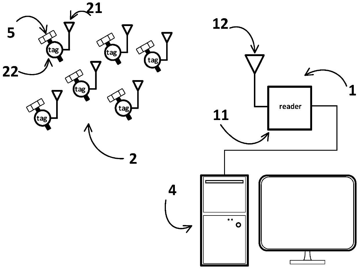
[0025] The system of the present invention is used to detect the state of the fastener. When the fastener is in a fastened state, the RFID chip reader and RFID tag are in a normal communication state; when the fastener is in a loose state, the RFID reader ( which is figure 1 reader) and RFID tag communication state is abnormal; the fasteners here can be thread fastening or buckle fastening, and this embodiment takes thread fastening as an example

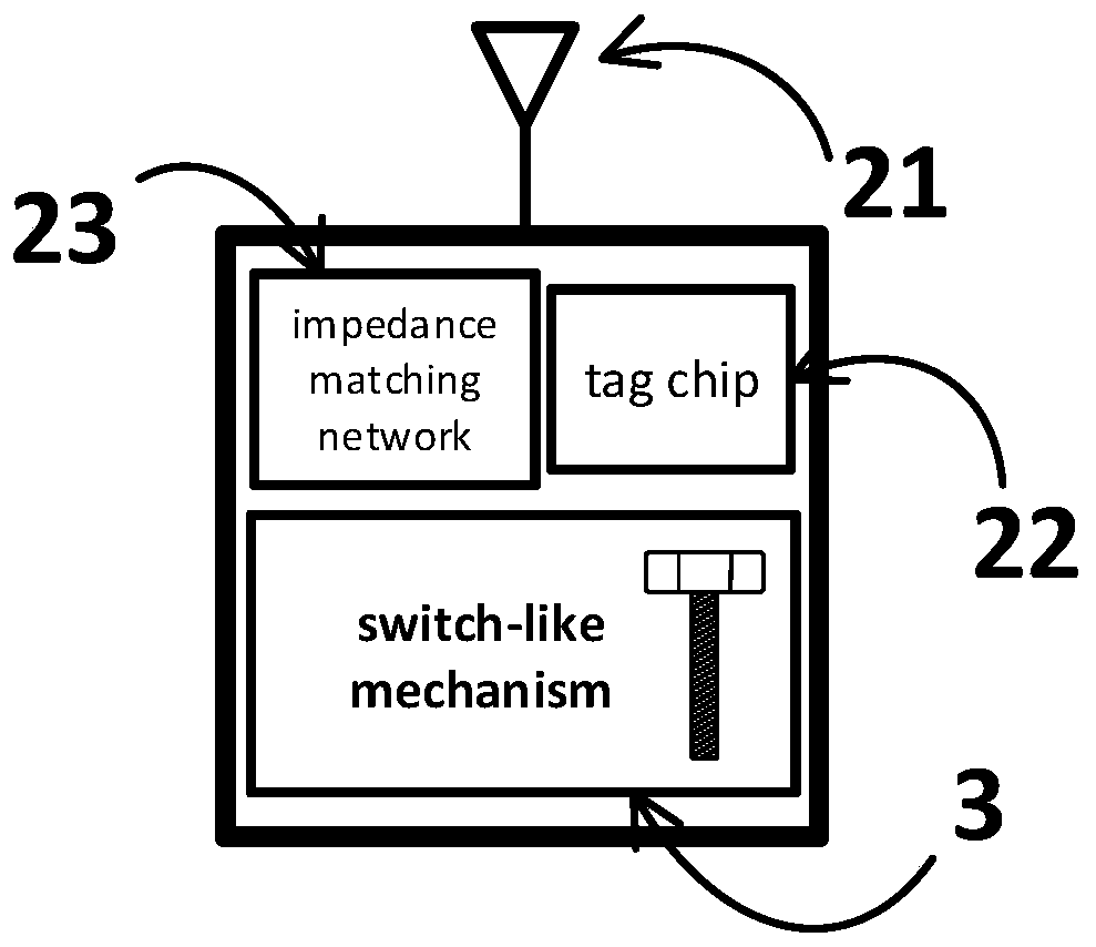
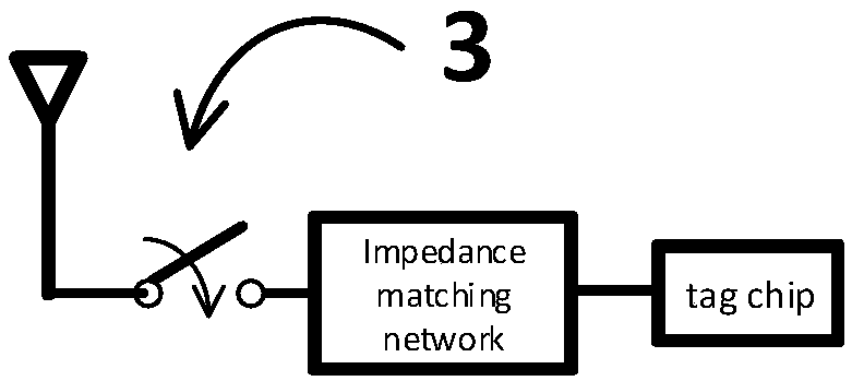
[0026] The present invention realizes the mechanical structural switch by simulating the screw (or a part of the structural screw head), and the RFID chip ( figure 2 Influenced by the working state of the tag chip) to realize the monitoring of the tightness of the screw, such as figure 1 Shown is th...


PUM


Abstract

The invention discloses an RFID (radio frequency identification) tag and a screw loosening state monitoring system based on the same and belongs to the field of screw state monitoring. The invention aims to solve the problems of leakage detection and false detection in the prior art. The structure of the RFID tag is mainly composed of an antenna and a tag chip; when the chip and the antenna are connected with each other, the tag can be accessed through a reader-writer; and a metal screw body serves as a switch-like mechanical structure and determines the switching of the disconnection state and connection state of the tag chip and the tag antenna, that is, the tag can be read and communicate with the reader-writer when the screw is firmly fixed; and the chip is disconnected from the tag antenna when the screw is loosened, and as a result, communication between the tag and the reader-writer is interrupted. The switch-like mechanical structure can be integrated in the tag antenna or an impedance matching network separately so as to form an integrated body with the tag, and therefore, the reliability of screw state detection is improved.

Description

technical field [0001] The invention belongs to the field of screw state monitoring, in particular to a method and a system for detecting the tightening / relaxing state of a screw through the communication transition between an RFID tag and an RFID reader. Background technique [0002] Automatically monitoring the mechanical condition of certain structures is becoming increasingly necessary, especially in industrial or vehicular environments. In fact, the loose state of the screw can greatly reduce the reliability of the system, and it can also endanger the safety. [0003] Manual inspection by an operator is a possible solution, with physical marking from the outside, for example, a spiral of colored sticky material can be used to detect the working condition of a screw. However, for large structures, such as the inspection of fixing screws at the rear of a train, manual inspections can take a long time. Another possible solution would be to use a vision system capable of ...

Claims


Application Information

Patent Timeline
IPC IPC(8): G01M13/00G06K17/00
CPCG01M13/00G06K17/0022
Inventor 文光俊殷丹胡伟李镇兵
Owner UNIV OF ELECTRONICS SCI & TECH OF CHINA
Learn More