Valve detection method and valve detection system

A detection system and detection method technology, applied in the field of valve detection, can solve problems such as large errors, and achieve the effect of reducing detection errors and improving detection accuracy

Inactive Publication Date: 2019-09-20
TIANJIN TRINOVA AUTOMOTIVE TECH CO LTD
View PDF7 Cites 6 Cited by
  • Summary
  • Abstract
  • Description
  • Claims
  • Application Information

AI Technical Summary

Problems solved by technology

Since the cross-sectional area of ​​the orifice is different under different openings of the valve, it is assumed that the cross-sectional area of ​​the orifice is a fixed value, and there is a large error in the detection of the flow coefficient.

Method used


Image

  • Valve detection method and valve detection system
  • Valve detection method and valve detection system
  • Valve detection method and valve detection system

Examples


Embodiment 1

[0031] like figure 2 As shown, the valve testing method provided by the embodiment of the present invention includes the following steps: detecting the valve core position of the tested valve 800, and calculating the orifice cross-sectional area of ​​the tested valve 800; The position of the spool can calculate the cross-sectional area of ​​the orifice between the spool and the inner wall of the valve cavity;

[0032] Measure the inlet pressure and outlet pressure of the tested valve 800, and calculate the pressure difference between the inlet pressure and outlet pressure;

[0033] Calculate the flow coefficient of the valve 800 under test.

[0034] Specifically, the formula for calculating the discharge coefficient is: Among them, Q is the liquid flow rate; C q is the flow coefficient, ρ is the density of the brake fluid, Δρ is the pressure difference between the inlet pressure and the outlet pressure, and A is the cross-sectional area of ​​the orifice.

[0035] Further...

Embodiment 2

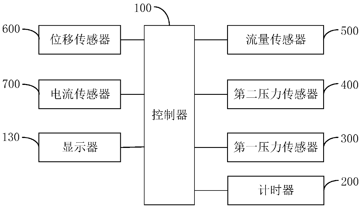
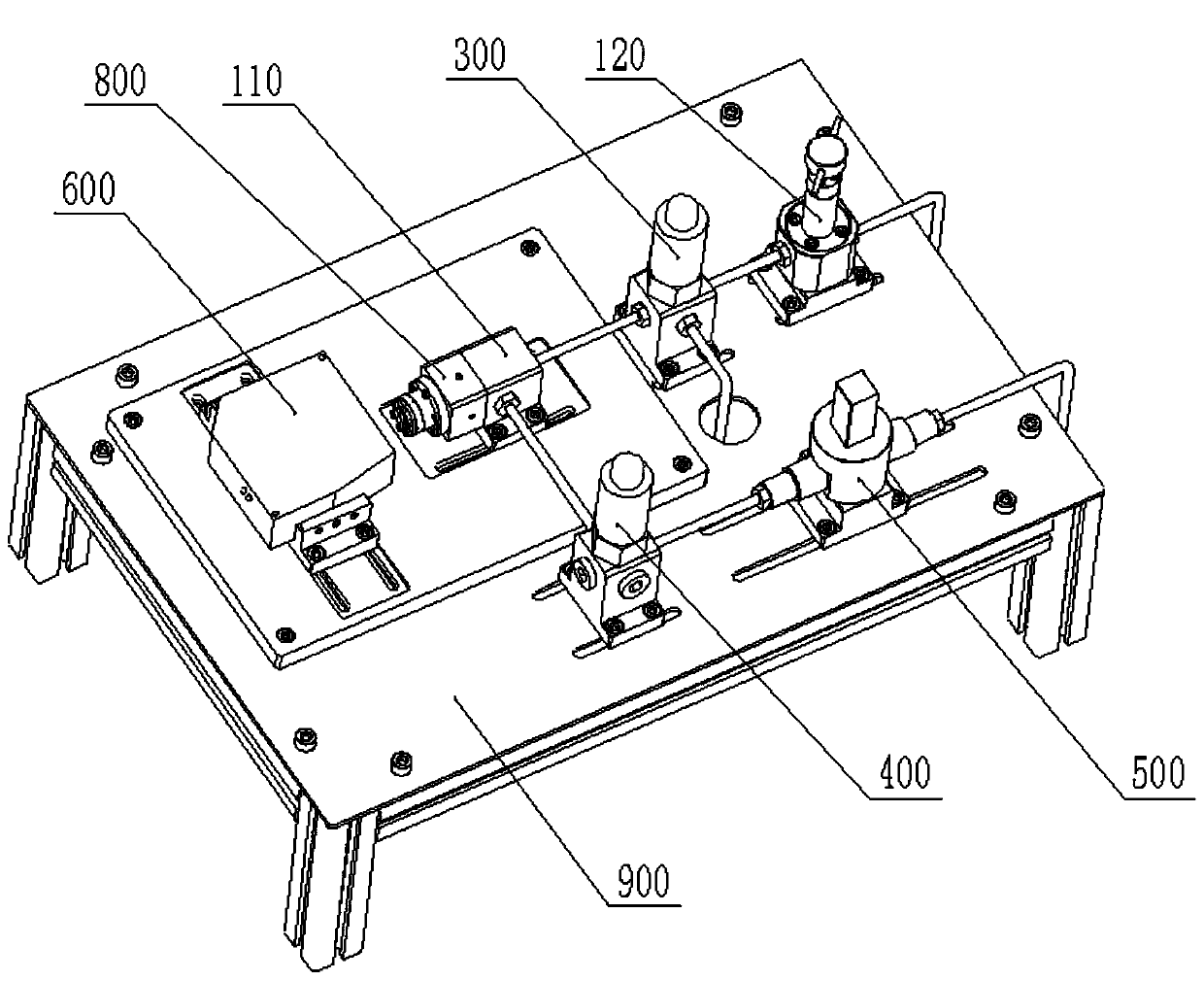
[0043] like figure 1 As shown, the valve detection system provided by the embodiment of the present invention includes: a controller 100, a first pressure sensor 300, a second pressure sensor 400, a flow sensor 500 and a displacement sensor 600, the first pressure sensor 300, the second pressure sensor 400 , the flow sensor 500 and the displacement sensor 600 are respectively connected to the controller 100; the first pressure sensor 300 is used to detect the liquid inlet pressure of the tested valve 800; the second pressure sensor 400 is used to detect the liquid outlet pressure of the tested valve 800; The flow sensor 500 is used to detect the liquid flow of the tested valve 800 ; the displacement sensor 600 is used to detect the displacement of the valve core of the tested valve 800 .

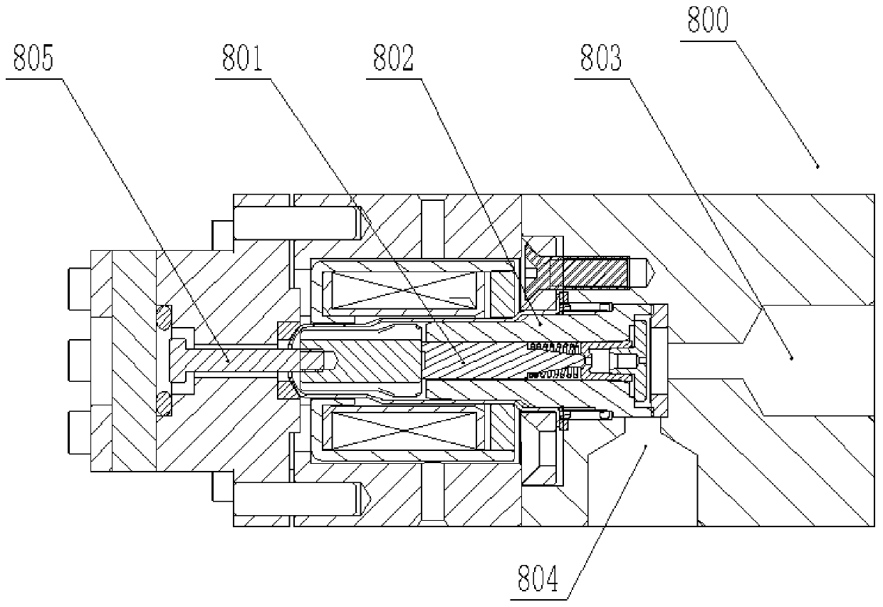
[0044] Specifically, the displacement sensor 600 is a laser displacement sensor, the valve under test 800 is a solenoid valve, the valve under test 800 includes: a moving assembly 801 and a fi...


PUM


Abstract

The invention provides a valve detection method and a valve detection system, and relates to the technical field of valve detecting. The valve detection method provided by the invention comprises the steps that the position of the valve element of a detected valve is detected, and the sectional area of the orifice of the detected valve is calculated; from the valve cavity size and the valve element position of the detected valve, the sectional area of the orifice between the valve element and the inner wall of the valve cavity is calculated; the inlet pressure and the outlet pressure of the detected valve are measured, and the pressure difference between the inlet pressure and the outlet pressure is calculated; and the flow coefficient of the detected valve is calculated. According to the invention, the valve detection method alleviates the technical problem of large error of valve detection in the prior art; the flow coefficient of the detected valve under different opening degrees can be calculated; and the detection accuracy of the flow coefficient is improved.

Description

technical field [0001] The invention relates to the technical field of valve detection, in particular to a valve detection method and a valve detection system. Background technique [0002] The existing fluid force testing devices measure the fluid pressure at both ends of the valve core, and then obtain the fluid force by multiplying the pressure by the area, and assume that the cross-sectional area of ​​the orifice is a constant value, so according to the formula Solve for the flow coefficient. Among them, C q is the flow coefficient, Q is the liquid flow rate, ρ is the liquid density, Δρ is the pressure difference at both ends of the valve core, and A is the cross-sectional area of ​​the orifice. Because the cross-sectional area of ​​the orifice is different under different opening degrees of the valve, there is a large error in the detection of the flow coefficient assuming that the cross-sectional area of ​​the orifice is a constant value. Contents of the invention...

Claims


Application Information

Patent Timeline
Patent Type & Authority Applications(China)
IPC IPC(8): G01M13/003
CPCG01M13/003
Inventor 方继根王西峰吴进军田月高祥李小康
Owner TIANJIN TRINOVA AUTOMOTIVE TECH CO LTD
Why Eureka
Try Eureka