Control circuit and chip

A technology for controlling circuits and chips, applied in circuit devices, emergency protection circuit devices, electrical components, etc., can solve problems such as limiting the flexibility of chip application, and achieve simple and reliable design circuits, high application flexibility, and reduction of chip pins. Effect

Pending Publication Date: 2019-09-20
杭州必易微电子有限公司
View PDF0 Cites 6 Cited by
  • Summary
  • Abstract
  • Description
  • Claims
  • Application Information

AI Technical Summary

Problems solved by technology

The function of the chip can only be limited, and only one of the protection functions can be selected, which greatly limits the flexibility of the chip application

Method used


Image

  • Control circuit and chip
  • Control circuit and chip
  • Control circuit and chip

Examples


Embodiment Construction

[0044] Preferred embodiments of the present invention will be described in detail below in conjunction with the accompanying drawings.

[0045] In order to further understand the present invention, the preferred embodiments of the present invention are described below in conjunction with examples, but it should be understood that these descriptions are only to further illustrate the features and advantages of the present invention, rather than limiting the claims of the present invention.

[0046] The description in this part is only for several typical embodiments, and the present invention is not limited to the scope of the description of the embodiments. The mutual replacement of the same or similar prior art means and some technical features in the embodiments is also within the scope of the description and protection of the present invention.

[0047] "Coupling" or connection in the specification includes both direct connection and indirect connection, such as connection ...


PUM


Abstract

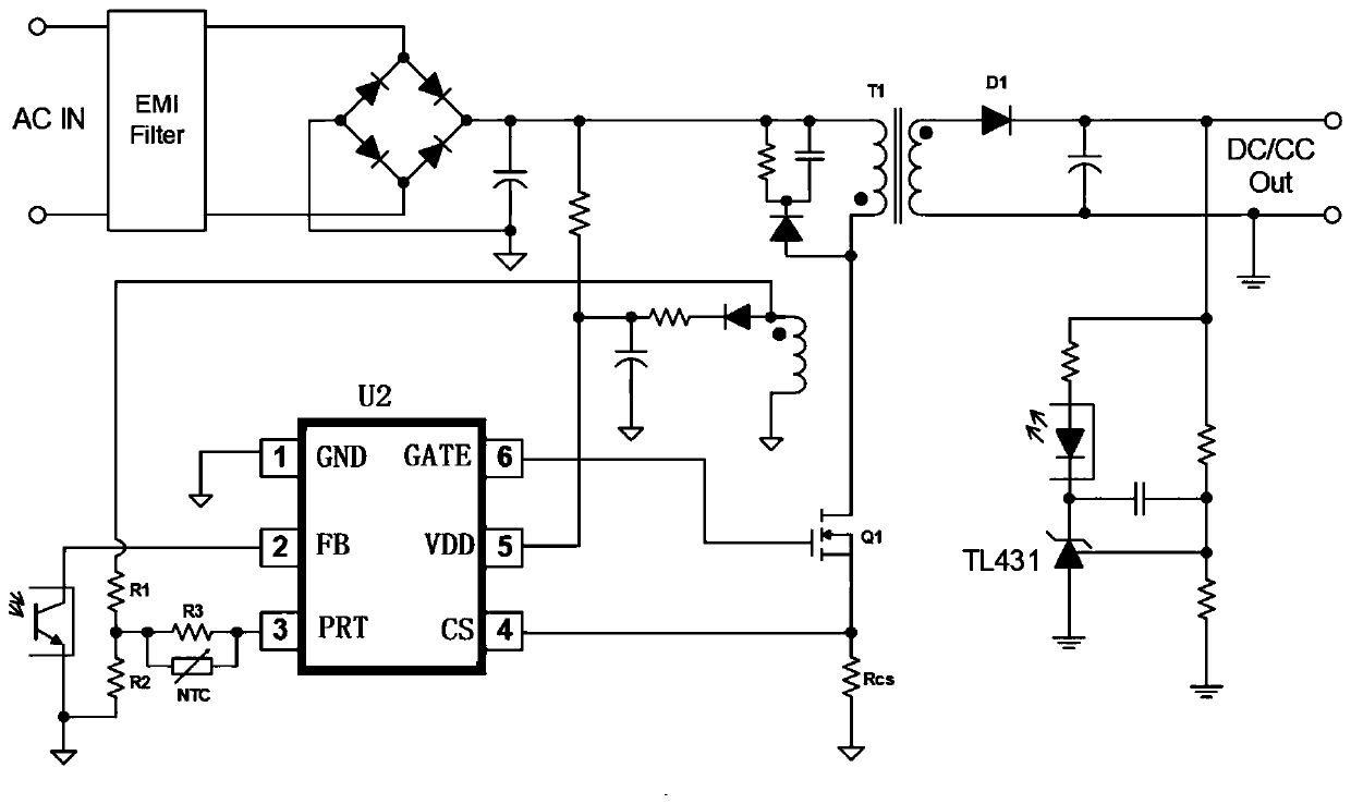
The invention discloses a control circuit and a chip. The control circuit comprises the chip. The chip comprises a reuse pin. The reuse pin is coupled to a thermosensitive element, a first voltage divider resistor and a second voltage divider resistor. Under a first state, the chip is coupled to the thermosensitive element through the reuse pin to judge temperature state of a circuit system so as to realize over-temperature protection detection of the chip; and under a second state, the chip is coupled to the first voltage divider resistor and the second voltage divider resistor through the reuse pin to realize at least one of overvoltage protection detection and undervoltage protection detection of the output voltage and demagnetization detection. The control circuit and the chip can reduce pin bits of the chip and avoid the problem of incomplete functions caused by insufficient pin bits by integrating different functions of pin bits. The control circuit is concise and reliable, integrates functions of over-temperature protection, overvoltage / under-voltage protection and demagnetization detection, is complete in functions and is large in application flexibility.

Description

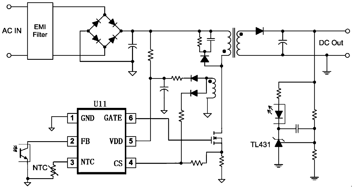
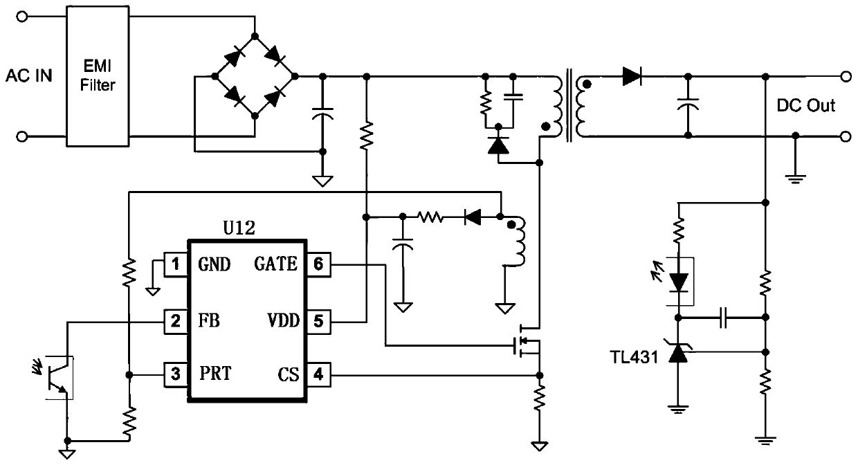
technical field [0001] The invention belongs to the technical field of electronic circuits, and relates to a chip and a control circuit. Background technique [0002] figure 1 It is a schematic circuit diagram of an existing control chip that performs over-temperature protection OTP through pins; please refer to figure 1 , the chip U11 instills a fixed current to the external NTC through the third pin. Since the impedance of the NTC changes with temperature, detecting the potential of pin 3 can determine the temperature state of the system, thereby realizing the function of over-temperature protection (OTP). [0003] figure 2 It is a schematic circuit diagram of an existing control chip for over-voltage protection / under-voltage protection and degaussing detection through pins; please refer to figure 2 , the third pin of the chip U12 samples the voltage of the auxiliary winding through two resistor dividers, so as to realize the output voltage over-voltage protection / und...

Claims


Application Information

Patent Timeline
Patent Type & Authority Applications(China)
IPC IPC(8): H02H5/04H02H7/125
CPCH02H5/042H02H7/125
Inventor 俞秀峰张波蓝舟
Owner 杭州必易微电子有限公司
Why Eureka
Try Eureka