Convenient-to-use clamping device for numerically-controlled machine tool

A technology of clamping device and numerical control machine tool, which is applied in the direction of positioning device, clamping, metal processing machinery parts, etc., can solve the problems of troublesome use, time-consuming and labor-intensive work, workpiece turnover, etc., and achieve the advantages of convenient use, easy manufacturing and time saving Effect

Inactive Publication Date: 2019-09-24
湛方林
View PDF9 Cites 8 Cited by
  • Summary
  • Abstract
  • Description
  • Claims
  • Application Information

AI Technical Summary

Problems solved by technology

[0003] In order to overcome the fact that the existing clamping devices for CNC machine tools usually adopt a traditional structure, the workpiece cannot be turned over during the processing, and the workpiece needs to be disassembled and assembled many times before the other surfaces of the workpiece can be processed, which is troublesome to use , time-consuming and labor-intensive shortcomings, therefore, the technical problem of the present invention is: to provide an easy-to-use clamping device for CNC machine tools that can flip the workpiece and save time and effort

Method used


Image

  • Convenient-to-use clamping device for numerically-controlled machine tool
  • Convenient-to-use clamping device for numerically-controlled machine tool
  • Convenient-to-use clamping device for numerically-controlled machine tool

Examples


Embodiment 1

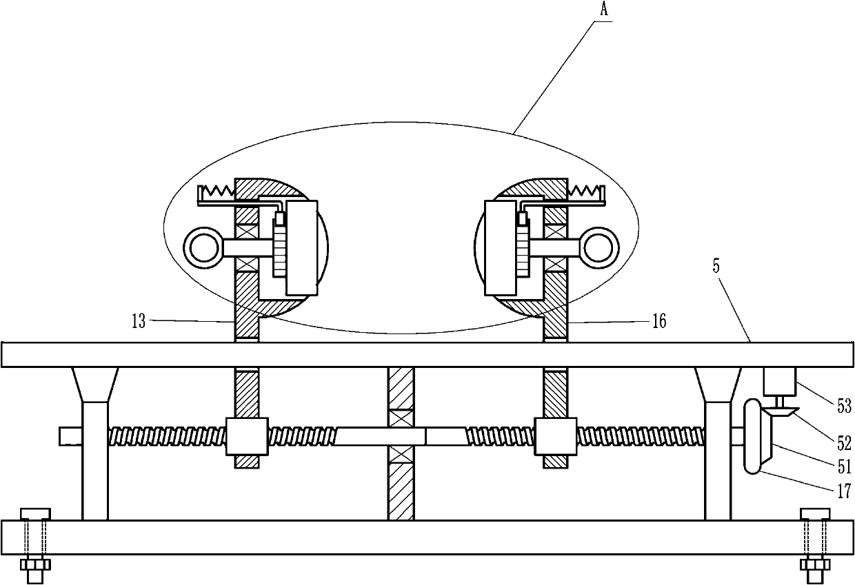
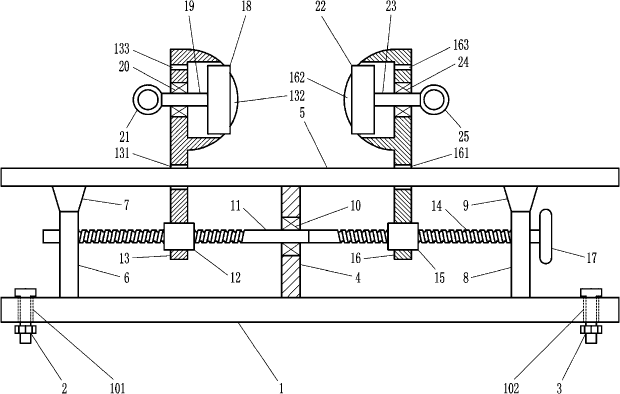
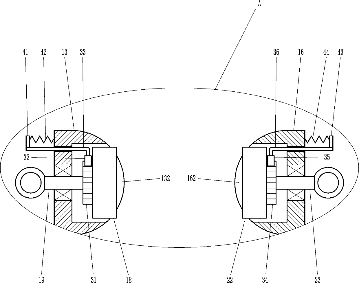
[0019] An easy-to-use clamping device for CNC machine tools such as Figure 1-3As shown, it includes base 1, first large bolt 2, second large bolt 3, large support plate 4, large guide rod 5, first bearing seat 6, first inverted trapezoidal block 7, second bearing seat 8, the first Two inverted trapezoidal blocks 9, the first large bearing 10, the first large screw mandrel 11, the first large nut 12, the first large P-shaped plate 13, the second large screw rod 14, the second large nut 15, the second large P Shaped plate 16, rotating wheel 17, the first pressing plate 18, the first rotating shaft 19, the second large bearing 20, the first grab ring 21, the second pressing plate 22, the second rotating shaft 23, the third large bearing 24 and the second Grab ring 25, the left end of the base 1 has a first large through hole 101, the first large bolt 2 is located in the first large through hole 101, the right end of the base 1 has a second large through hole 102, and the second ...

Embodiment 2

[0021] An easy-to-use clamping device for CNC machine tools such as Figure 1-3 As shown, it includes base 1, first large bolt 2, second large bolt 3, large support plate 4, large guide rod 5, first bearing seat 6, first inverted trapezoidal block 7, second bearing seat 8, the first Two inverted trapezoidal blocks 9, the first large bearing 10, the first large screw mandrel 11, the first large nut 12, the first large P-shaped plate 13, the second large screw rod 14, the second large nut 15, the second large P Shaped plate 16, rotating wheel 17, the first pressing plate 18, the first rotating shaft 19, the second large bearing 20, the first grab ring 21, the second pressing plate 22, the second rotating shaft 23, the third large bearing 24 and the second Grab ring 25, the left end of the base 1 has a first large through hole 101, the first large bolt 2 is located in the first large through hole 101, the right end of the base 1 has a second large through hole 102, and the second...

Embodiment 3

[0024] An easy-to-use clamping device for CNC machine tools such as Figure 1-3As shown, it includes base 1, first large bolt 2, second large bolt 3, large support plate 4, large guide rod 5, first bearing seat 6, first inverted trapezoidal block 7, second bearing seat 8, the first Two inverted trapezoidal blocks 9, the first large bearing 10, the first large screw mandrel 11, the first large nut 12, the first large P-shaped plate 13, the second large screw rod 14, the second large nut 15, the second large P Shaped plate 16, rotating wheel 17, the first pressing plate 18, the first rotating shaft 19, the second large bearing 20, the first grab ring 21, the second pressing plate 22, the second rotating shaft 23, the third large bearing 24 and the second Grab ring 25, the left end of the base 1 has a first large through hole 101, the first large bolt 2 is located in the first large through hole 101, the right end of the base 1 has a second large through hole 102, and the second ...


PUM


Abstract

The invention relates to a clamping device for a numerically-controlled machine tool, in particular to a convenient-to-use clamping device for the numerically-controlled machine tool. Therefore, the invention aims to solve the technical problem of providing a convenient-to-use clamping device which can be used for turning workpieces and save time and labor for the numerically-controlled machine tool. The convenient-to-use clamping device for the numerically-controlled machine tool comprises a base, a first large bolt, a second large bolt, a large supporting plate, a large guide rod, a first bearing seat, a first inverted trapezoidal block, a second bearing seat, a second inverted trapezoidal block and the like, wherein a first large through hole is formed in the left end of the base, and the first large bolt is positioned in the first large through hole. According to the convenient-to-use clamping device for the numerical control machine tool, the workpieces can be turned in the machining process, the other surfaces of the workpieces can be machined without detaching the workpieces, the clamping device is convenient to use, the time and the labor are saved, the production and development of enterprises are facilitated, and the structure is simple.

Description

technical field [0001] The invention relates to a clamping device for a numerically controlled machine tool, in particular to an easy-to-use clamping device for a numerically controlled machine tool. Background technique [0002] CNC machine tool is a high-precision and high-efficiency automatic machine tool, equipped with multi-station turret or power turret, has a wide range of processing performance, and can process linear cylinders, oblique cylinders, arcs and various threads, grooves, Complex workpieces such as worms have various compensation functions such as linear interpolation and circular interpolation, and have played a good economic effect in the mass production of complex parts. The workpiece is processed. The existing clamping device for CNC machine tools usually adopts the traditional structure. During the processing, the workpiece cannot be turned over, and the workpiece needs to be disassembled and assembled many times before the other surfaces of the workpi...

Claims


Application Information

Patent Timeline
Patent Type & Authority Applications(China)
IPC IPC(8): B23Q3/06
CPCB23Q3/06
Inventor 湛方林
Owner 湛方林
Why Eureka
Try Eureka