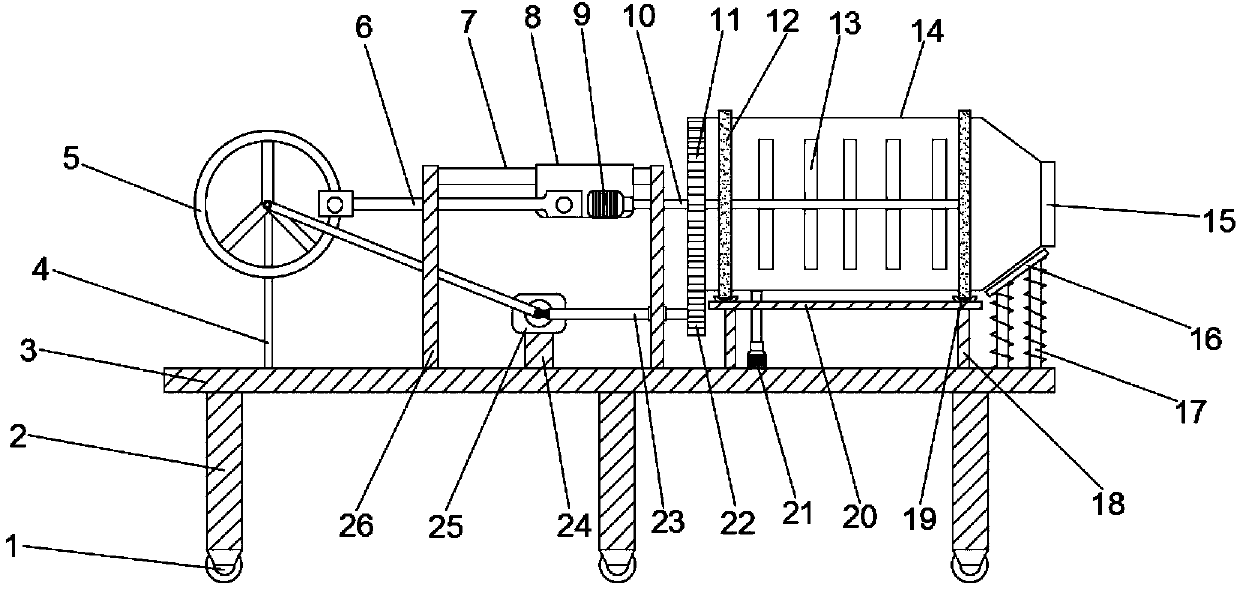
Building construction concrete mixer

A technology for building construction and concrete, applied in cement mixing devices, clay preparation devices, unloading devices, etc., can solve the problems of insufficient mixing, inconvenient discharging, and single mixing method.

Inactive Publication Date: 2019-09-24
湖北乾奥建设工程有限公司
0 Cites 1 Cited by

AI-Extracted Technical Summary

Problems solved by technology

[0003] The purpose of the present invention is to solve the problems of single mixing method, insufficient mixing, inc...

Abstract

A building construction concrete mixer comprises a first supporting plate. Six fixed plates arranged in a rectangular shape are arranged below the first supporting plate, and every two adjacent fixed plates are symmetric about the center line of the first supporting plate. A universal wheel is arranged on the lower portion of each fixed plate. A first fixed rod, two parallel third fixed rods and four second fixed rods arranged in a rectangular shape are sequentially arranged on the upper surface of the supporting plate from left to right. A rotating disc is arranged on the side, away from the first supporting plate, of the first fixed rod, and the first fixed rod is rotationally connected with the rotating disc through a first rotating shaft. A fixed block is arranged between the two third fixed rods. The upper surface of the fixed block is fixedly connected with a second rotating motor. The second rotating motor is rotationally connected with the first rotating shaft on the rotating disc through a belt. The building construction concrete mixer is convenient to operate and move, discharging is rapid, diversified mixing manners are achieved, and mixing is uniform and thorough.

Application Domain

Discharging apparatusCement mixing apparatus

Technology Topic

Architectural engineeringBuilding construction +1

Image

  • Building construction concrete mixer
  • Building construction concrete mixer

Examples

  • Experimental program(1)

Example Embodiment

[0014] The following will clearly and completely describe the technical solutions in the embodiments of the present invention with reference to the accompanying drawings in the embodiments of the present invention. Obviously, the described embodiments are only some, not all, embodiments of the present invention.
[0015] In describing the present invention, it should be understood that the terms "upper", "lower", "front", "rear", "left", "right", "top", "bottom", "inner", " The orientation or positional relationship indicated by "outside", etc. is based on the orientation or positional relationship shown in the drawings, and is only for the convenience of describing the present invention and simplifying the description, rather than indicating or implying that the referred device or element must have a specific orientation, so as to Specific orientation configurations and operations, therefore, are not to be construed as limitations on the invention.
[0016] refer to Figure 1-2 , a mixer for building construction concrete, comprising a first support plate 3, six fixed plates 2 arranged in a rectangular shape are arranged below the first support plate 3, and every two adjacent fixed plates 2 are connected to the first A support plate 3 is symmetrical to the center line, and the bottom of each fixed plate 2 is provided with universal wheels 1 for easy movement. The third fixed rod 26 and four second fixed rods 18 arranged in a rectangular shape, the first fixed rod 4 is provided with a rotating disk 5 on the side away from the first support plate 3, and the first fixed rod 4 passes through the first rotating shaft Rotately connected with the rotating disc 5, a fixed block 24 is arranged between the two third fixed rods 26, the upper surface of the fixed block 24 is fixedly connected with a second rotating motor 25, and the second rotating motor 25 is connected to the rotating disc 5 by a belt. The first rotating shaft on the top is rotationally connected, the output end of the second rotating motor 25 is provided with a moving rod, and the end of the moving rod away from the second rotating motor 25 is provided with a first bevel gear 27, and the moving rod is away from the side of the rotating disk 5 A rotating rod 23 is provided, and the rotating rod 23 runs through the inner side wall of the third fixed rod 26 and extends to the outside of the third fixed rod 26. The end of the rotating rod 23 near the moving rod is provided with a first bevel gear 27 matched with the first bevel gear. Two bevel gears 28, the rotating rod 23 is provided with the second gear 22 away from the end of the moving rod, and the inner side walls of the two third fixed rods 26 away from the first support plate 3 are fixedly connected with the sliding track 7, and the sliding track 7 is provided with a sliding track 7. Block 8, a movable rod 6 is arranged between the moving block 8 and the rotating disk 5, and the movable rod 6 is respectively connected in rotation with the rotating disk 5 and the moving block 8 through the second rotating shaft and the third rotating shaft, each second One end of the fixed rod 18 away from the first support plate 3 is fixedly connected with a third support plate 20, the upper surface of the third support plate 20 is provided with two second support plates 19 arranged in parallel, and the top of the third support plate 20 is provided with a third support plate 20. There is a stirring box 14, the outer wall of the stirring box 14 is provided with an annular plate 12 matched with the second support plate 19, and the side of the stirring box 14 near the third fixed rod 26 is provided with a first gear 22 matched with the second gear. The gear 11 can make the concrete mix evenly and thoroughly through the left and right reciprocating movement of the stirring rod 10 and the rotation in the opposite direction of the self-propagation and the mixing box 14.
[0017] Stirring box 14 is provided with inlet and outlet 15 on one side away from the third fixed rod 26, is positioned at the upper surface of the first support plate 3 between the second fixed rods 18 and is provided with push rod motor 21, and the inside of moving block 8 is provided with First rotating motor 9, the output end of the first rotating motor 9 is provided with stirring rod 10, and stirring rod 10 runs through the inner sidewall of moving block 8, the third fixed rod 26 and stirring box 14 and extends to the inside of stirring box 14, stirring The shaft of the rod 10 is provided with a plurality of symmetrical stirring rods 13, and the upper surface of the first support plate 3 located below the inlet and outlet 15 is provided with a buffer device 17, and the end of the buffer device 17 away from the first support plate 3 is fixedly connected together. There is a buffer plate 16, which plays a buffering role when the material is poured. The buffer device 17 is composed of an elastic rod and a spring wound on the elastic rod. The inner surface of the second support plate 19 is provided with evenly distributed balls, which is beneficial to the stirring box 14. Rotate, the side wall of the third fixed rod 26 between the second rotating motor 25 and the rotating disc 5 is provided with a movable groove matched with the movable rod 6, and the mixing box 14 is close to the side wall of the third fixed rod 26 A circular groove is provided, and the first rotating motor 9, the second rotating motor 25 and the push rod motor 21 are all electrically connected with an external power supply through wires.
[0018] In the present invention, when stirring operation is required, the stirring raw materials are transported into the stirring box 14, and the second rotating motor 25 drives the rotating disk 5 to rotate through the belt, and then the movable rod 6 is moved, and the movable rod 6 drives the moving block 8 Moving back and forth on the sliding track 7, the first rotating motor 9 inside the moving block 8 drives the stirring rod 10 and the stirring rod 13 to rotate in a circle, and the second rotating motor 25 passes through the first bevel gear 27 and the second bevel gear 28. The function makes the rotating rod 23 rotate, drives the second gear 22 to rotate, the second gear 22 drives the first gear 11 to rotate, and then the stirring box 14 rotates, and the left and right circular rotation of the stirring rod 10 and the stirring rod 13, the stirring box 14 Rotate in the opposite direction, the concrete is fully mixed. After the mixing is completed, the push rod motor 21 tilts the mixing box 14, and pours the mixed concrete from the inlet and outlet 15. The buffer plate 16 and the buffer device 15 can buffer the mixing box 14. , the second support plate 19 supports the stirring box 14 and the balls on the inner surface of the second support plate 19 facilitate the rotation of the stirring box 14 .

PUM

no PUM

Description & Claims & Application Information

We can also present the details of the Description, Claims and Application information to help users get a comprehensive understanding of the technical details of the patent, such as background art, summary of invention, brief description of drawings, description of embodiments, and other original content. On the other hand, users can also determine the specific scope of protection of the technology through the list of claims; as well as understand the changes in the life cycle of the technology with the presentation of the patent timeline. Login to view more.
Why Eureka
Try Eureka