
Throttle valve and hydraulic system

A throttling valve and throttling channel technology, which is applied in the direction of fluid pressure actuators, valve details, control valves, etc., can solve the problems of unable to throttle and block, and achieve the effect of simple structure and high compactness

Pending Publication Date: 2019-09-24
杭州力龙液压有限公司
View PDF0 Cites 3 Cited by
  • Summary
  • Abstract
  • Description
  • Claims
  • Application Information

AI Technical Summary

Problems solved by technology

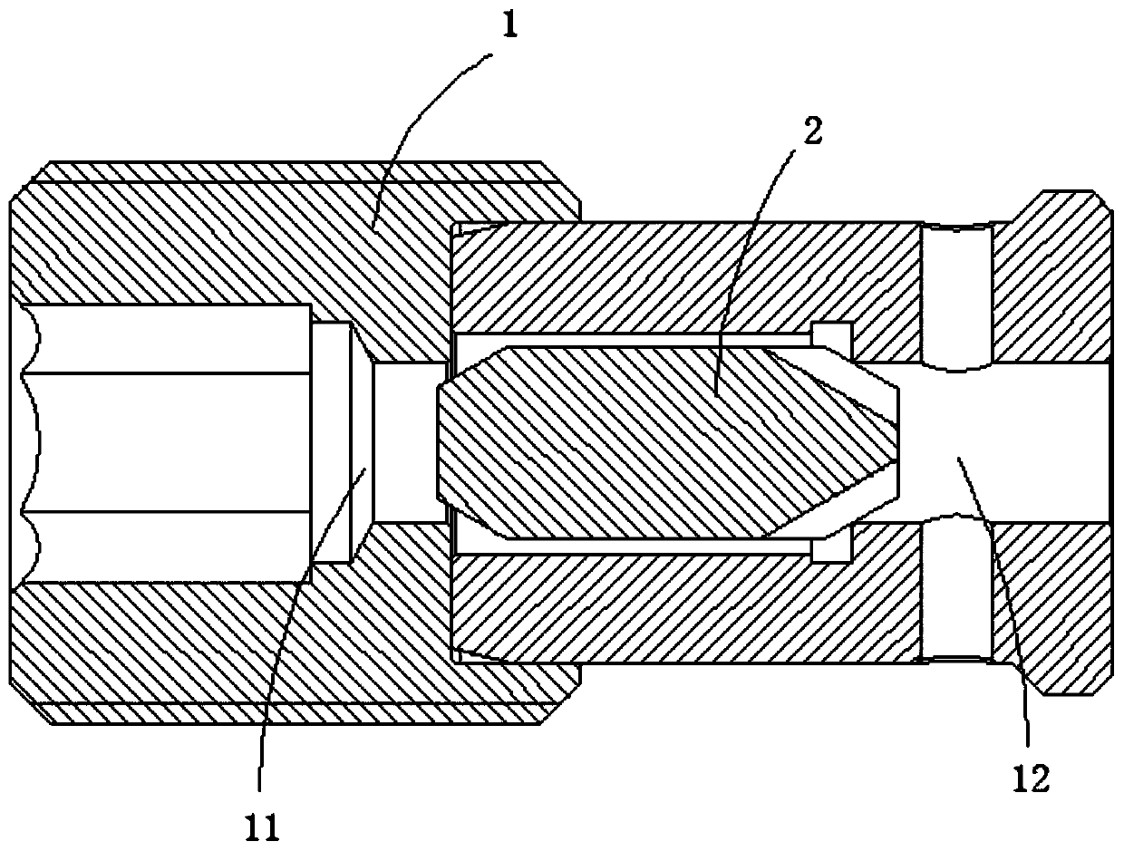
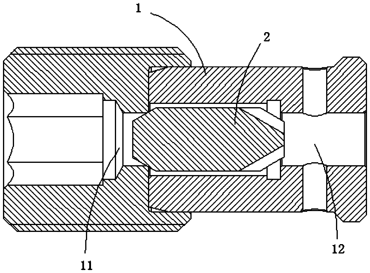
[0005] The object of the present invention is to provide a throttle valve and a hydraulic system, so as to alleviate the problem that the throttle valve in the prior art cannot throttle the liquid flowing in a specific direction and block the flow in the direction opposite to the specific direction. liquid technical issues

Method used


Image

  • Throttle valve and hydraulic system
  • Throttle valve and hydraulic system
  • Throttle valve and hydraulic system

Examples


Embodiment Construction

[0036] The technical solutions of the present invention will be clearly and completely described below in conjunction with the accompanying drawings. Apparently, the described embodiments are some of the embodiments of the present invention, but not all of them. Based on the embodiments of the present invention, all other embodiments obtained by persons of ordinary skill in the art without making creative efforts belong to the protection scope of the present invention.

[0037] In the description of the present invention, it should be noted that the orientations or positional relationships indicated by the terms "center", "inner" and "outer" are based on the orientations or positional relationships shown in the drawings, and are only for the convenience of describing the present invention and simplified descriptions, rather than indicating or implying that the device or element referred to must have a specific orientation, be constructed and operate in a specific orientation, a...


PUM


Abstract

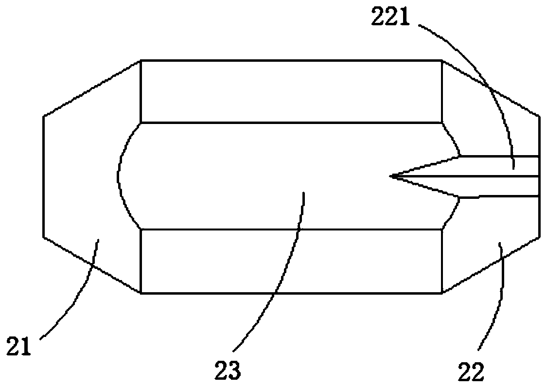
The invention relates to the technical field of valves, in particular to a throttle valve and a hydraulic system. The throttle valve includes a valve body and a valve element; the two ends of the valve body are provided with a first valve port and a second valve port, the valve element includes a first end portion adjacent to the first valve port, a second end portion adjacent to a second valve port and a main body portion, and the valve element is provided with a throttle passage; when liquid flows from the first valve port to the second valve port, the second end portion can abut against the second valve port, one end of the throttle passage is in communication with the first valve port through an inner cavity of the valve body, and the other end of the throttle passage is in communication with the second valve port; and when the liquid flows from the second valve port to the first valve port, the first end portion can abut against the first valve port and seal the first valve port. The hydraulic system includes the above throttle valve. According to the throttle valve and the hydraulic system, throttle of the liquid flowing from the first valve port to the second valve port can be carried out, the liquid flowing from the second valve port to the first valve port can be blocked, and the compactness is further improved easily.

Description

technical field [0001] The invention relates to the technical field of valves, in particular to a throttle valve and a hydraulic system. Background technique [0002] The throttle valve is a valve that controls the flow of liquid by changing the throttle section or throttle length. At present, there are mainly two types of throttle valves used in hydraulic systems. The first type is a two-way throttle valve. The orifice on the two-way throttle valve flows out, that is, the two-way throttle valve can play a two-way throttling effect on the liquid; the second is a one-way throttle valve, when the liquid passing through the valve body flows in a specific direction, the liquid It can only flow out from the orifice of the one-way throttle valve to throttle the liquid, and when the liquid flows in the opposite direction to the specific direction, the one-way throttle valve opens without any throttling of the liquid Function, that is, the one-way throttle valve can only play a on...

Claims


Application Information

Patent Timeline
IPC IPC(8): F16K17/24F16K15/02F16K27/02F16K47/04F15B13/02
CPCF16K17/24F16K15/021F16K47/04F16K27/0209F16K27/0254F15B13/023F15B13/027
Inventor 马宁包丽伟李新峰
Owner 杭州力龙液压有限公司
Learn More