Permanent magnet motor rotor structure and mounting method

A technology of rotor structure and permanent magnet motor, applied in the direction of magnetic circuit shape/style/structure, electromechanical device, manufacturing motor generator, etc., can solve the problems of complicated working procedures, high cost, and easy noise generated by the motor, and achieve low operating speed Effects of noise reduction, magnetic flux leakage reduction, and increased magnetic resistance

Pending Publication Date: 2019-09-24
NIDEC KAIYU AUTO ELECTRIC JIANGSU
View PDF0 Cites 4 Cited by
  • Summary
  • Abstract
  • Description
  • Claims
  • Application Information

AI Technical Summary

Problems solved by technology

[0002] Most of the existing small permanent magnet motor rotors adopt the magnetic cylinder structure. Compared with the bow-shaped magnetic steel structure, the magnetic cylinder structure is more expensive. The outside of the magnetic cylinder is directly exposed in the air gap, and the debris generated by the rotor during operation Directly into the air gap of the motor, the motor is prone to noise
For rot

Method used


Image

  • Permanent magnet motor rotor structure and mounting method
  • Permanent magnet motor rotor structure and mounting method
  • Permanent magnet motor rotor structure and mounting method

Examples


Embodiment Construction

[0024] Below by embodiment, the present invention will be further described.

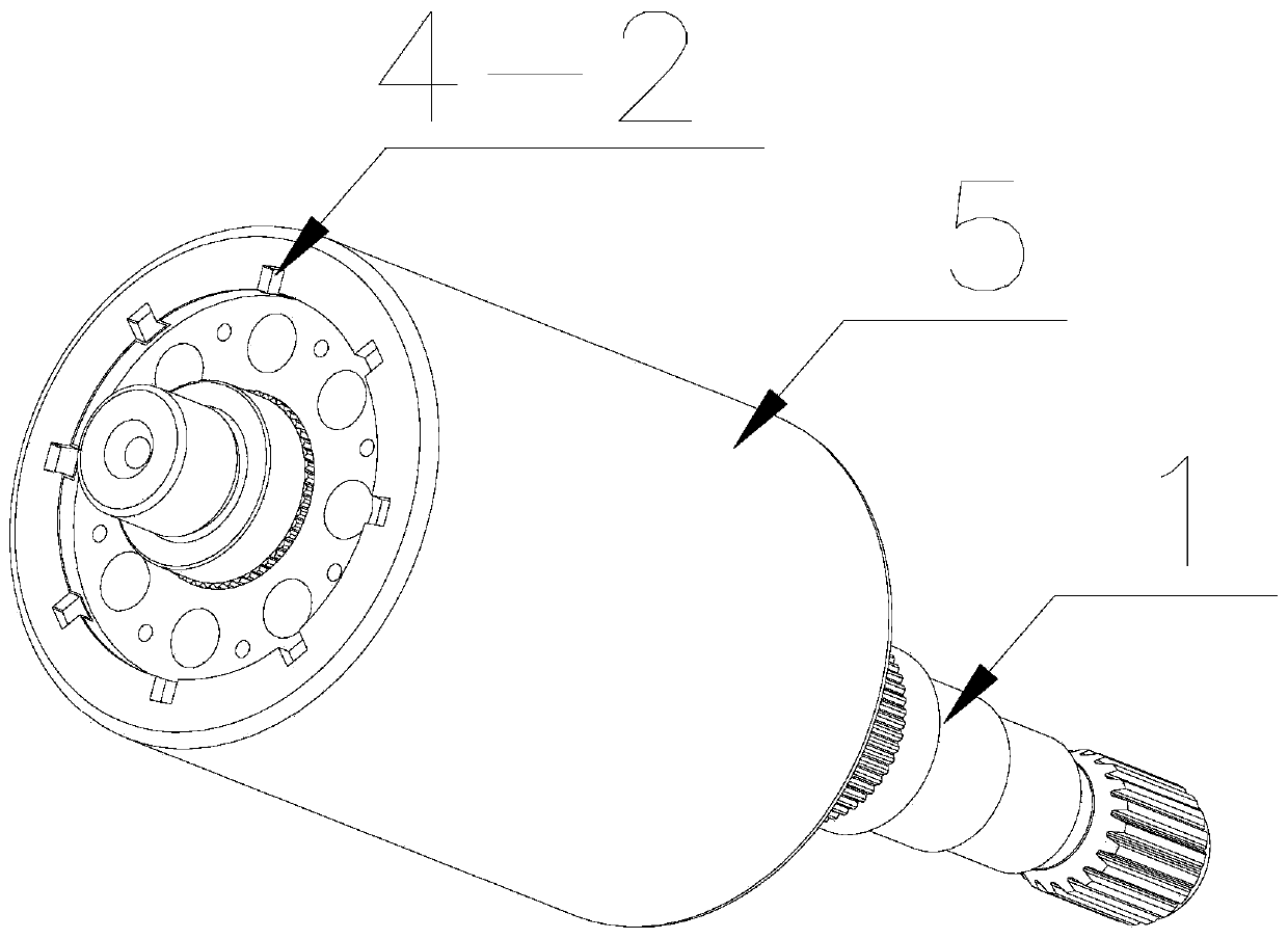
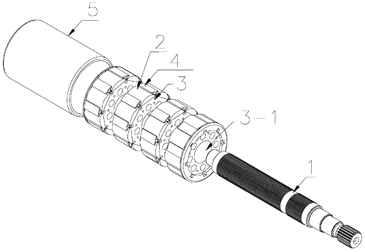
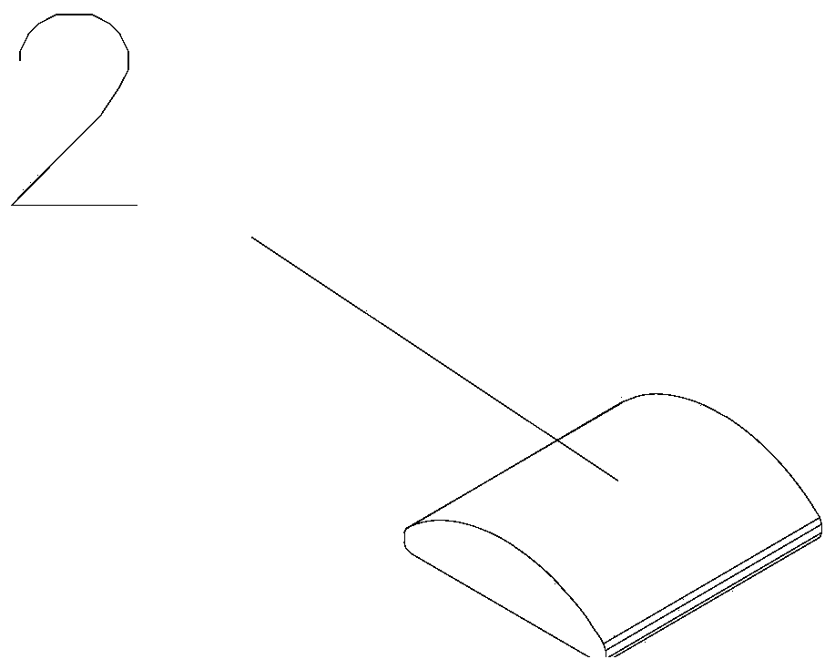
[0025] Such as Figure 1~8 As shown, a permanent magnet motor rotor structure includes: a rotating shaft 1, a magnetic steel 2, a rotor core 3, a magnetic steel fixing part 4 and a rotor sheath 5, the center of the rotor core 3 is provided with a through hole 3-1, and the rotor iron The section of the core 3 is a regular polygon. The outer periphery of the rotor core 3 is provided with a magnetic isolation groove 6 at the side junction, and the magnetic steel fixing part 4 is injected into the magnetic isolation groove 6. The magnetic steel fixing part 4 is T-shaped, and the magnetic steel fixing part 4 is T-shaped. The steel 2 is inserted into the cavity 7 formed by two adjacent T-shaped magnetic steel fixtures 4 and the surface of the rotor core 3, and the rotating shaft 1 is pressed into the center through hole 3-1 of the rotor core 3, and the feature is that the magnetic steel The fixing part 4...


PUM

PropertyMeasurementUnit
Radiusaaaaaaaaaa
Outer diameteraaaaaaaaaa
Thicknessaaaaaaaaaa

Abstract

The invention discloses a permanent magnet motor rotor structure. The structure comprises a rotating shaft, a magnetic steel, a rotor iron core, magnetic steel fixing parts and a rotor sheath, wherein a through hole is formed at the center of the rotor core, the section of the rotor core is a regular polygon, and the periphery of the rotor iron core is provided with a magnetic isolation groove at the junction of the side edges. The magnetic steel fixing parts are partially injected into the magnetic isolation grooves, and the magnetic steel fixing parts are T-shaped; the magnetic steel is inserted into a cavity formed by the surfaces of every two adjacent T-shaped magnetic steel fixing parts and the surface of the rotor iron core, the rotating shaft is pressed into a central through hole of the rotor iron core, and the magnetic steel fixing parts further comprise side baffle rings arranged on the two sides of the rotor iron core; the rotor sheath is cylindrical, one side of the rotor sheath is provided with a closing opening which is preset to be closed up towards the circle center, and the closing opening is annular; the rotor core is sleeved by the rotor sheath, one side of the shell nosing is located on the shaft extension side, the other side of the rotor sheath is also folded towards the circle center, and the shell nosing is annular. The magnetic flux leakage rate is low, the materials are saved, and the working efficiency is high.

Description

technical field [0001] The invention relates to a permanent magnet motor rotor structure, which belongs to the field of motors. Background technique [0002] Most of the existing small permanent magnet motor rotors adopt the magnetic cylinder structure. Compared with the bow-shaped magnetic steel structure, the magnetic cylinder structure is more expensive. The outside of the magnetic cylinder is directly exposed in the air gap, and the debris generated by the rotor during operation Directly into the air gap of the motor, the motor is prone to noise. For rotors with surface-mounted magnetic steel, the rotor core generally uses dovetail grooves to fix the magnetic steel, and the magnetic resistance at the junction of the magnetic steel is very small, resulting in serious magnetic flux leakage. The straight sheath that is applied outside needs glue to fix, and its working procedure is complicated, and glue bonding is troublesome, and its quality is not stable. Contents of t...

Claims


Application Information

Patent Timeline
IPC IPC(8): H02K1/27H02K15/03
CPCH02K1/276H02K15/03H02K2213/03
Inventor 王咏涛邱高峰王朝海
Owner NIDEC KAIYU AUTO ELECTRIC JIANGSU
Why Eureka
Try Eureka