Low-speed torque motor with self-locking torque applicable to aerospace equipment

A technology of aerospace equipment and torque motors, applied in the field of torque motors, to meet the needs of driving and self-locking, easy installation, and small installation space

Inactive Publication Date: 2019-09-24
HARBIN INST OF TECH
View PDF6 Cites 2 Cited by
  • Summary
  • Abstract
  • Description
  • Claims
  • Application Information

AI Technical Summary

Problems solved by technology

[0003] As far as the current technology and existing products are concerned, there is no torque motor with power-off self-locking function that can meet the requirements of aerospace

Method used


Image

  • Low-speed torque motor with self-locking torque applicable to aerospace equipment
  • Low-speed torque motor with self-locking torque applicable to aerospace equipment
  • Low-speed torque motor with self-locking torque applicable to aerospace equipment

Examples


specific Embodiment approach 1

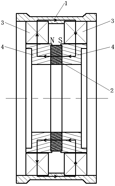
[0014] Specific implementation mode one: as figure 1 As shown, this embodiment describes a low-speed torque motor with self-locking torque suitable for aerospace equipment, including a casing 1, a magnetic steel 2, two sections of stator core 3, two sections of rotor core 4 and two sets of three-phase windings The two sections of rotor cores 4 are arranged coaxially (that is, they are arranged facing axially), the two sections of rotor cores 4 are provided with magnetic steel 2, and the outside of each section of rotor cores 4 is fitted with a stator core 3, The two sections of stator cores 3 are arranged coaxially (that is, they are arranged opposite to each other in the axial direction), and the two sections of stator cores 3 are connected by a magnetically permeable material (the purpose is to form a closed magnetic circuit), and each section of the stator core 3 Several large teeth and several small teeth are evenly distributed on the inner circumference of the inner circu...

specific Embodiment approach 2

[0015] Specific implementation mode two: as figure 1 As shown, this embodiment is a further description of specific embodiment 1. In order to meet the special environment of aerospace, the air gap between each stator core 3 and the corresponding rotor core 4 is 0.3~0.5mm (while the common The air gap between the stator and rotor iron cores of stepping motors is 0.03 ~ 0.05mm.Common stepping motors all try to design the positioning torque as small as possible in order to improve performance, and the present invention increases the positioning torque, Bigger is better, which is the complete opposite of design philosophy).

specific Embodiment approach 3

[0016] Specific implementation mode three: as figure 1 As shown, this embodiment is a further description of specific embodiment 1 or 2. The number of small teeth uniformly distributed on the inner peripheral surface of the stator core 3 and the uniformly distributed small teeth on the outer peripheral surface of the rotor core 4 The slot widths of several small teeth are larger than the tooth width of the small teeth (in order to maximize the no-load positioning torque of the motor).


PUM


Abstract

The invention relates to a low-speed torque motor with self-locking torque applicable to aerospace equipment, and belongs to the technical field of motors. Two rotor cores are coaxially arranged, magnetic steel is arranged between the two rotor cores, the outer side of each rotor core is sleeved with a stator core, the two stator cores are coaxially arranged, the two stator cores are connected through a magnetic conductive material, the inner circumferential surface of each stator core is provided with a plurality of uniformly distributed large and small teeth, the plurality of large and small teeth are alternately arranged one by one, the plurality of large and small teeth on the two stator cores are arranged in a one-to-one correspondence manner, the outer circumferential surface of each rotor core is also provided by a plurality of uniformly distributed small teeth, the plurality of small teeth on the two rotor cores are arranged in a one-to-one correspondence manner in the axial direction, each stator core and the corresponding rotor core are provided with an air gap therebetween, each stator core is assembled with a set of three-phase winding, and the same sequence number phases in the two sets of three-phase windings are opposite in magnetic potential. The torque motor with the power-off self-locking function can meet aerospace requirements.

Description

technical field [0001] The invention relates to a torque motor and belongs to the technical field of motors. Background technique [0002] When the aerospace equipment on the aerospace device is in a non-working dormant state, its position often needs to be locked to prevent its free movement from affecting its normal work. Usually, this requirement is met by additionally designing a locker on the drive unit of aerospace equipment. However, when the lock is unlocked or locked, it needs to be powered, which increases the energy consumption on the aerospace device. Moreover, the additional locking link does not meet the basic requirements of small size, light weight and high reliability for aerospace devices. If the torque motor of the drive unit in an aerospace equipment can have the functions of driving and power-off self-locking, avoiding additional design of the locker, it will be of great significance to the engineering application of aerospace equipment. [0003] With...

Claims


Application Information

Patent Timeline
IPC IPC(8): H02K21/14H02K21/02H02K1/27H02K1/14
CPCH02K1/146H02K1/2706H02K21/02H02K21/14H02K2201/03
Inventor 李勇马鹏程王宝超胡建辉王骞江善林马晶谭立英
Owner HARBIN INST OF TECH
Why Eureka
Try Eureka