Adjustable elliptical orbit lower limb rehabilitation wheelchair

An elliptical trajectory and adjustable technology, which is applied to patient chairs or special transport tools, vehicle ambulance, passive exercise equipment, etc., to meet individual needs and achieve the effect of easy operation

Inactive Publication Date: 2019-09-27
TIANJIN UNIV
8 Cites 2 Cited by

AI-Extracted Technical Summary

Problems solved by technology

In addition, these products can only be used for training and...

Abstract

The invention relates to an adjustable elliptical orbit lower limb rehabilitation wheelchair. The wheelchair comprises a frame, a seat, large wheels and an elliptical orbit implementation device, wherein the elliptical orbit implementation device comprises a fixing seat, a motor, a driven wheel, a belt, central shafts, crank rotating shafts, cranks, limit sliders, connecting rod supports, sliders, a pedal, a walking wheel, a collision bead limit structure and a limit hole. The output shaft of the motor transfers powder to the elliptical orbit driven wheel through the belt, the driven wheel is connected to the fixed seat through the central shaft, one offset crank slider mechanism is arranged on each of two sides of the driven wheel, the cranks on the two sides are connected with the central shaft and rotate with the driven wheel simultaneously, and the cranks on two sides are arranged at an included angle and provided with sliding grooves; one side of each limit slider is matched with the corresponding sliding groove and can slide along the sliding groove, the other end of each limit slider is connected with the corresponding connecting rod support through the crank rotating shaft, one end of each of connecting rod supports on two sides is connected with the corresponding limit slider through the crank rotating shaft, and the other end is connected with the walking wheel.

Application Domain

Technology Topic

Image

  • Adjustable elliptical orbit lower limb rehabilitation wheelchair
  • Adjustable elliptical orbit lower limb rehabilitation wheelchair
  • Adjustable elliptical orbit lower limb rehabilitation wheelchair

Examples

  • Experimental program(1)

Example Embodiment

[0022] Below in conjunction with specific embodiment the present invention is described in further detail:
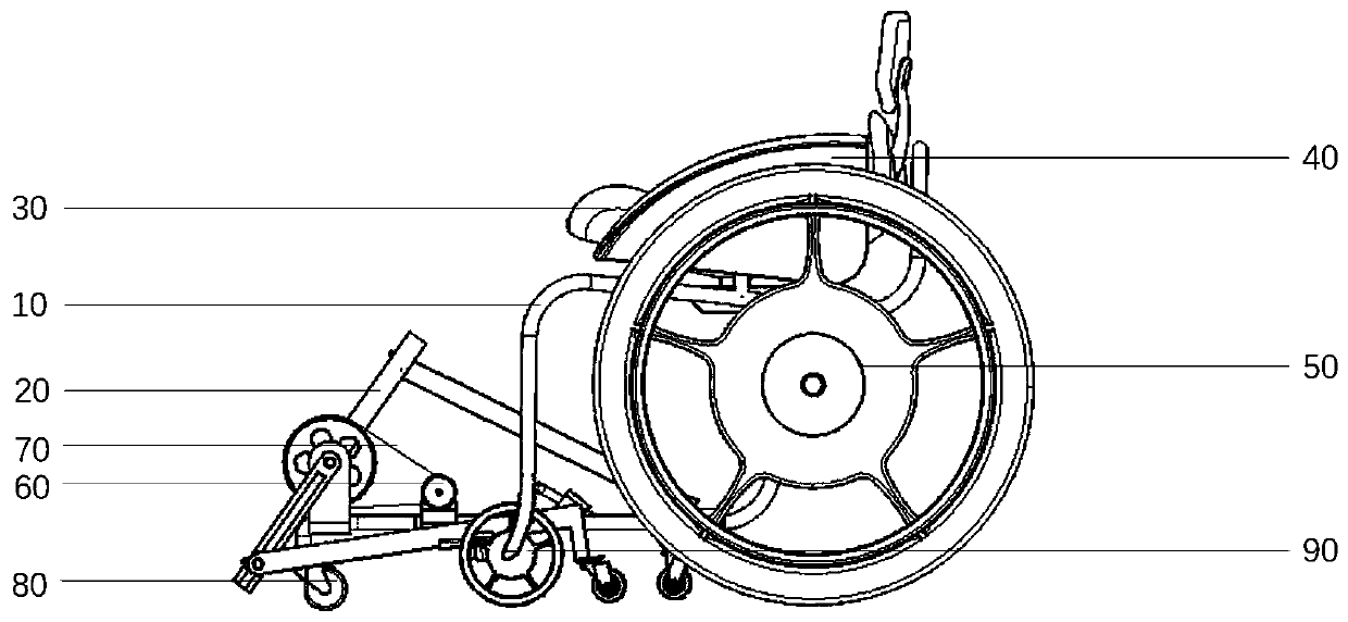
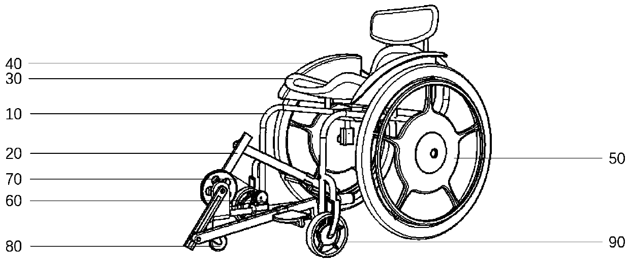
[0023] like figure 1 , the present invention is a lower limb rehabilitation wheelchair capable of realizing an adjustable elliptical trajectory, including a wheelchair part and an elliptical trajectory realization device, including a vehicle frame 10, a seat 30 and an armrest 40 fixed on the vehicle frame 10, and a large The wheels 50 are fixed on the vehicle frame 10 through shaft transmission, and the supporting wheels 90 and the guide wheels 80 are connected on the vehicle frame 10 by bolts. The elliptical track realizing device 20 is fixed on the vehicle frame 10 by bolts. The motor 60 is fixed on the vehicle frame 10 through bolt connection.
[0024] like figure 1 and Figure 4 , the adjustable elliptical trajectory lower limb rehabilitation wheelchair of the present invention, the patient sits on the wheelchair, puts both feet on the pedals of the elliptical trajectory realization device, and the elliptical trajectory realization device drives the patient's feet to move on the elliptical trajectory to achieve the purpose of rehabilitation . The device for realizing the elliptical trajectory is an offset crank slider mechanism. The output shaft of the motor 60 transmits power to the driven wheel 201 of the elliptical trajectory realization device through the belt 70 . The driven wheel 201 is connected to the fixed seat 211 through the central shaft 202, and the cranks 203 on both sides are connected to the fixed seat 211 through the central shaft 202, and the cranks on both sides are arranged at an angle of 180 degrees, and can rotate simultaneously with the driven wheel 201. There is an inverted trapezoidal chute above the cranks 203 on both sides. One side of the limit slider 204 fits with the chute and can slide along the direction of the chute in the chute. The limit slider is squeezed and tightened by the bolt 205. limit. The other side of the limit slider 204 is connected with the link bracket 207 through the crank shaft 206 . The link brackets 207 on both sides are L-shaped, and one end of the link bracket 207 is connected with the limit slider 204 through the crank shaft 206, and the other end is connected with the action wheel 213 by bolts. Pedal 210 is connected with slide block 208 by rotating shaft, and slide block 208 is c-shaped, and can fit and slide on above with connecting rod support 207, carries out limit and fixes by touch bead limit structure 212 and limit hole 209. The schematic diagram of the bead limit structure is as follows Image 6 and Figure 7. On slider 208 as Figure 7 The limiting structure 212 shown has a trapezoidal hole on the slider 208 , in which a spring 2121 , a touch bead 2122 and a closing cover 2123 are placed. One side of the spring 2121 is in contact with the bead 2122, and the other side is in contact with the closing cover 2123, and the closing cover 2123 is screwed into the limiting hole. Under the active force of the spring 2121, the touch bead 2122 can only expose a certain size under the restriction of the trapezoidal hole, and the exposed part of the touch bead 2122 falls into the limit hole 209 on the connecting rod bracket 207, which acts as a limit, so that the slider Cannot slide. When the sliding block 208 is pushed under a large force, the bumper ball will be retracted into the trapezoidal hole under extrusion, so that the sliding block 208 slides along the connecting rod 207 until it encounters the next limiting hole. By changing the positions of the slider 208 and the limit slider 204, the elliptical trajectory can be adjusted to adapt to the actual situation of the patient. The device 20 for realizing the ellipse trajectory connects the fixing seat 211 with the vehicle frame 10 through bolts.
[0025] The vehicle frame 10 of the present invention is formed by bending and welding aluminum pipes, and the seat 30 and the armrest 40 are formed by injection molding. The elliptical trajectory realization device is cut and welded from aluminum sheet. Finally, assemble all parts together.
[0026] How to use this product:
[0027] When using and installing the adjustable elliptical track lower limb rehabilitation wheelchair of the present invention, first, according to the suggestion of the rehabilitation doctor, adjust the slider 208 and the limit slider 204 on the elliptical track realization device 20 to a suitable position, and then make the elliptical track realization device run. The elliptical trajectory fits the patient's normal gait. Let the patient sit on the seat 30 of the wheelchair, and fix the patient's feet on the footrests 210 . When the power switch is turned on, the motor 60 drives the elliptical trajectory to realize the movement of the device, and then drives the patient to carry out rehabilitation training exercises.
[0028] Figure 4 It shows the movement process of the elliptical trajectory realization device 20 in the present invention. The motor 60 drives the driven wheel 201 on the elliptical trajectory realization device 20 to rotate through the belt 70, and then drives the crank 203, the link bracket 207 to move, and finally drives the patient through the pedal 210 The foot realizes the elliptical trajectory movement. By adjusting the positions of the slider 208 and the limit slider 204, the elliptical trajectory can be adjusted within a certain range according to the needs of the patient, making it more in line with the requirements of the patient.
[0029] In summary, the adjustable elliptical trajectory lower limb rehabilitation wheelchair of the present invention combines the elliptical trajectory realization device with the wheelchair, and can adjust the elliptical trajectory according to the actual situation of the patient. In addition, the present invention changes the previous lower limb rehabilitation products that can only be performed in a fixed place The limitation of rehabilitation training can facilitate the movement to different places to meet the individual needs of patients.
[0030] Although the present invention has been described above in conjunction with the drawings, the present invention is not limited to the above-mentioned specific embodiments, and the above-mentioned specific embodiments are only illustrative, rather than restrictive. Under the condition of not departing from the gist of the present invention, many changes can also be made, and these all belong to the protection of the present invention.

PUM

no PUM

Description & Claims & Application Information

We can also present the details of the Description, Claims and Application information to help users get a comprehensive understanding of the technical details of the patent, such as background art, summary of invention, brief description of drawings, description of embodiments, and other original content. On the other hand, users can also determine the specific scope of protection of the technology through the list of claims; as well as understand the changes in the life cycle of the technology with the presentation of the patent timeline. Login to view more.

Similar technology patents

Classification and recommendation of technical efficacy words

  • Meet individual needs
  • Easy to operate

Method and device for automatically recommending application

InactiveCN102567511AMeet individual needsImprove recommendation efficiency and coverageSpecial data processing applicationsPersonalizationData set
Owner:QIZHI SOFTWARE (BEIJING) CO LTD
Why Eureka
Try Eureka