
Six-rod stretching and drawing overall robot

A kind of overall tension and robot technology, applied in manipulators, motor vehicles, program-controlled manipulators, etc., can solve the problems of complex structure and difficult deformation.

Active Publication Date: 2019-09-27
HARBIN INST OF TECH
View PDF5 Cites 9 Cited by
  • Summary
  • Abstract
  • Description
  • Claims
  • Application Information

AI Technical Summary

Problems solved by technology

[0006] In order to solve the problem that the traditional robot has a complex structure and is not easy to deform in the existing tensegrity structure robot, the present invention further provides a six-bar tensioner overall robot

Method used


Image

  • Six-rod stretching and drawing overall robot
  • Six-rod stretching and drawing overall robot
  • Six-rod stretching and drawing overall robot

Examples


specific Embodiment approach 1

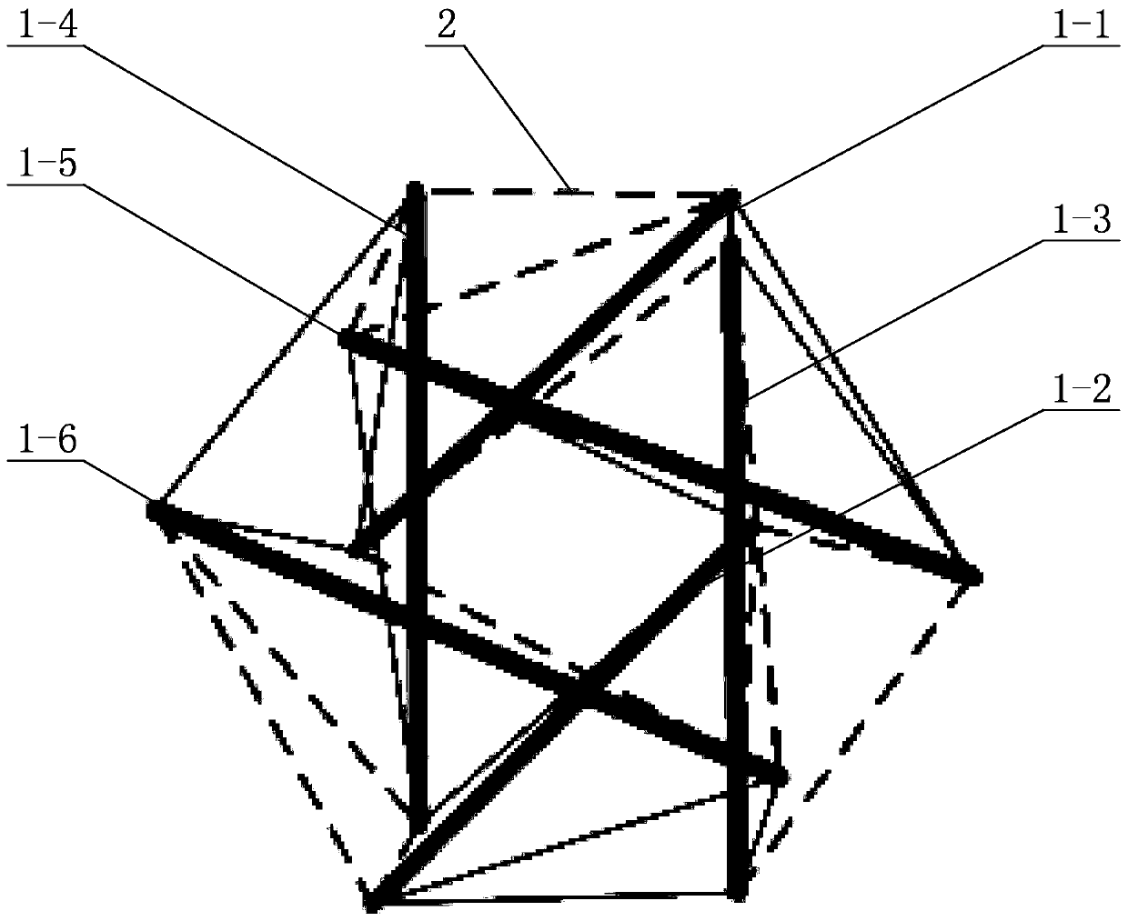
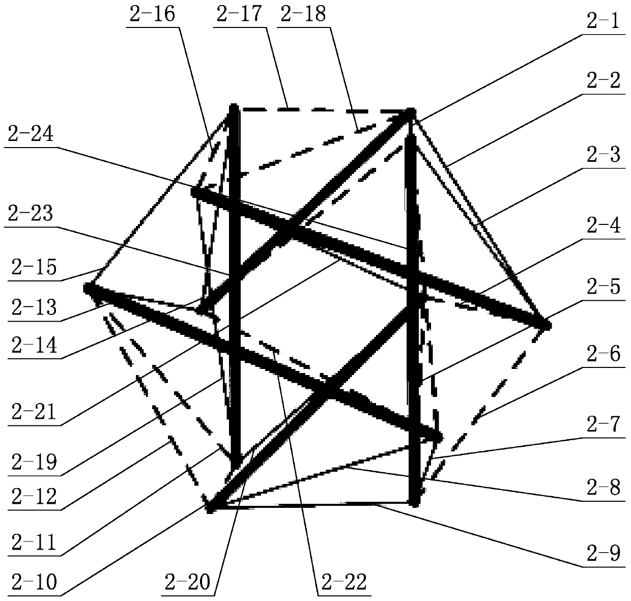
[0027] Specific implementation mode one: combine Figure 1 to Figure 7 Describe this embodiment, a six-bar tensioned integral robot of this embodiment, it includes 6 rigid rods 1 and 24 flexible ropes 2, and the 6 rigid rods 1 and 24 flexible ropes 2 form a class Icosahedral tensegrity structure;

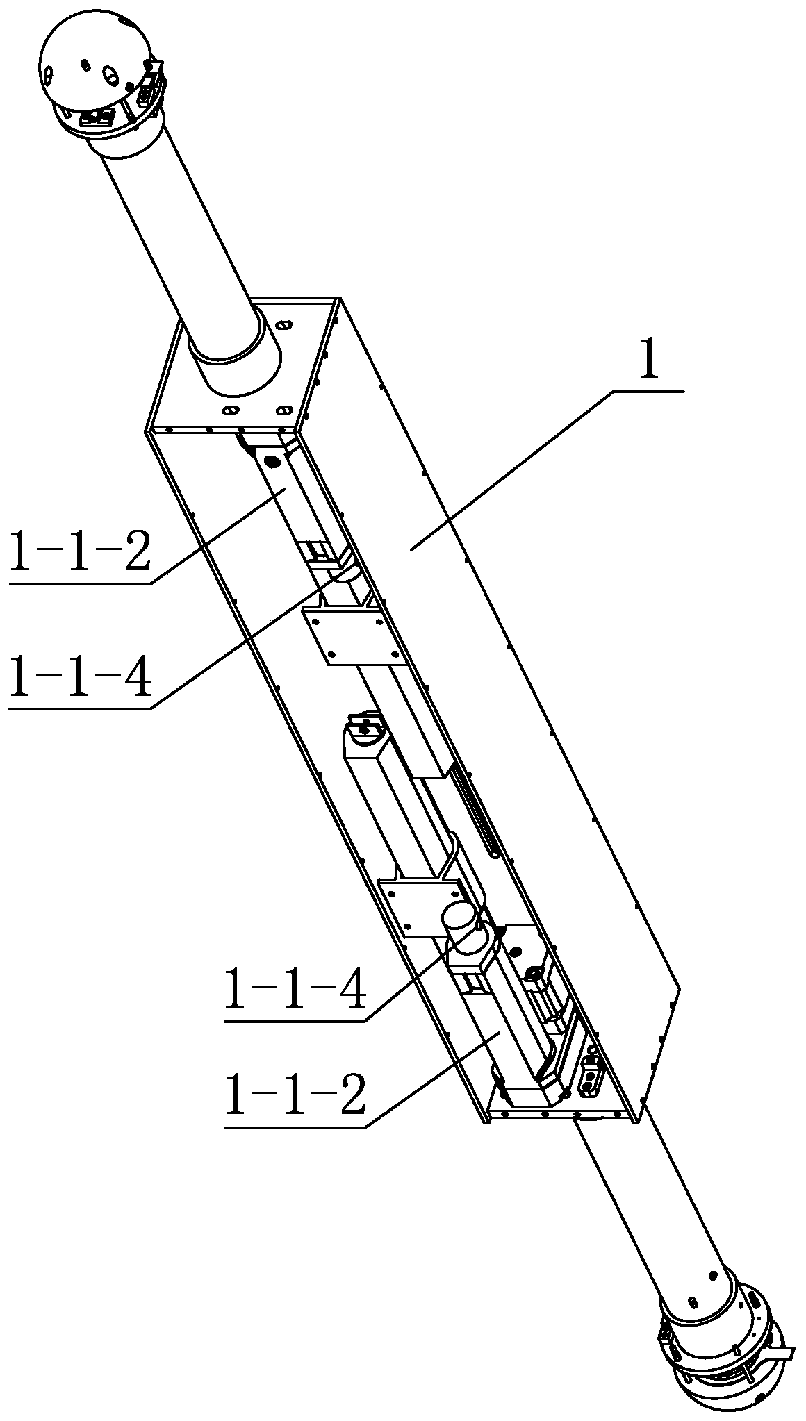
[0028] The structure of the six rigid rods 1 is the same, each rigid rod 1 includes a central assembly and two end assemblies, and the two end assemblies are symmetrically arranged at the left and right ends of the central assembly, and the central assembly includes a box body 1-1- 1 and 2 drive units, the box 1-1-1 is a closed cuboid structure, the 2 drive units are set inside the box 1-1-1, and the 2 drive units are respectively located in the box 1-1-1 left and right ends;

[0029]The six rigid rods 1 are respectively the first rod 1-1, the second rod 1-2, the third rod 1-3, the fourth rod 1-4, the fifth rod 1-5 and the sixth rod The rods 1-6, the first rod 1-1 and the second ...

specific Embodiment approach 2

[0040] Specific implementation mode two: combination Figure 4 To illustrate this embodiment, the box body 1-1-1 of this embodiment includes 6 connecting plates, and the 6 connecting plates are respectively 2 front and rear connecting plates 1-1-1-1, and 2 left and right connecting plates 1-1- 1-2 and 2 upper and lower connecting plates 1-1-1-3, 2 front and rear connecting plates 1-1-1-1 are located at the front and rear ends of the box body 1-1-1, 2 left and right connecting plates 1-1 -1-2 is located at the left and right ends of the box body 1-1-1, and the two upper and lower connecting plates 1-1-1-3 are located at the upper and lower ends of the box body 1-1-1. So arranged, 6 connecting plates are bolted together to form the outer surface of the closed central assembly. Other compositions and connections are the same as in the first embodiment.

specific Embodiment approach 3

[0041] Specific implementation mode three: combination image 3 and Figure 4 Describe this embodiment, the two driving units of this embodiment are respectively installed on the inner end faces of two upper and lower connecting plates 1-1-1-3, and each driving unit includes an electric push rod 1-1-2, a push rod bracket 1-1-3 and the rope connection clamp 1-1-4, the motor bottom of the electric push rod 1-1-2 is installed on the inner end face of the left and right connecting plates 1-1-1-2, the push rod bracket 1-1 -3 is installed on the adjacent upper and lower connecting plates 1-1-1-3, the electric push rod 1-1-2 is fixed on the push rod bracket 1-1-3, and the rope connection clamp 1-1-4 is set on The end of the piston rod of the electric push rod 1-1-2. Other compositions and connections are the same as those in Embodiment 1 or Embodiment 2.

[0042] The manufacturer and model of the electric push rod 1-1-2 of the present embodiment are Longxiang (hardware), and the s...


PUM


Abstract

The invention provides a six-rod stretching and drawing overall robot and relates to the field of six-rod stretching and drawing overall robot machine system design. The six-rod stretching and drawing overall robot solves the problems that an existing stretching and drawing overall structure robot is complex in structure and not easy to deform. The six-rod stretching and drawing overall robot comprises six rigid rod pieces and twenty four flexible ropes. The six rigid rod pieces and the twenty four flexible ropes form an icosahedron stretching and drawing overall structure. Each rigid rod piece comprises a center assembly and two end portion assemblies, wherein the two end portion assemblies are symmetrically arranged at the left end and the right end of the center assembly, the center assembly comprises a box body and two drive units, the two drive units are arranged in the box body, the two drive units are located at the left end and the right end of the box body, each drive unit comprises an electric pushing rod, a pushing rod support and a rope connecting hoop, the bottom of a motor of the electric pushing rod is installed on the end faces of the inner sides of left and right connecting plates, and the electric pushing rod is connected with the corresponding flexible rope through the corresponding rope connecting hoop. The six-rod stretching and drawing overall robot can reduce the stress on legs of the robot on the floor to the greatest extent.

Description

technical field [0001] The invention relates to the field of mechanical system design of a six-bar tension integral robot, in particular to a six-bar tension integral robot. Background technique [0002] In recent years, scientists have been searching for a new type of planetary probe with light weight, simple structure, deformability and strong environmental robustness. The variable structure robot based on the tensegrity structure design is a network structure composed of discontinuous compression bars and continuous tension cables. With a high strength-to-mass ratio, it can manufacture lightweight robots. At the same time, it has strong deformability, and has certain compression and impact resistance, which can improve the protection of the robot itself and the load it carries. [0003] In the field of engineering, the structural form and inherent properties will make the control effect significantly different, but the inertia and stiffness of many structures themselves ...

Claims


Application Information

Patent Timeline
Patent Type & Authority Applications(China)
IPC IPC(8): B25J11/00B25J9/12B62D57/02B64G1/16
CPCB25J11/00B25J9/12B25J9/104B62D57/02B64G1/16
Inventor 魏承潘冬陈磊董晓姚程赵阳
Owner HARBIN INST OF TECH
Learn More