
Shaver head structure and shaver

A razor and hole-one technology, applied in the field of razor head structure and razor, can solve the problems of increasing the difficulty of manufacturing and installation, complex structure of parts, poor structural strength, etc., to reduce the design complexity, Guaranteed shaving experience and reduced manufacturing costs

Pending Publication Date: 2019-09-27
ZHEJIANG ZHIBO ELECTRICAL APPLIANCE TECH CO LTD
View PDF2 Cites 1 Cited by
  • Summary
  • Abstract
  • Description
  • Claims
  • Application Information

AI Technical Summary

Problems solved by technology

[0003] Generally, the coordination between the spherical floating support with spherical concave and the floating support plate with spherical support is set in the cutter head housing to realize the floating of the cutter head, such as a spherical floating frame published by the application number CN201410750358.6 In this patent, the arrangement of the spherical concave position and the spherical support is not very reasonable. The spherical concave position and the spherical support are located in the area between the driving gear and the floating support plate, so that the spherical support has an overall The problem of small size, poor structural strength, and easy damage greatly reduces the service life of the cutter head. Due to the small size of the spherical floating bracket, it is inconvenient to install; The correlation is high, that is to say, the existence of the spherical floating bracket must require structural changes or addition of components in the other parts of the cutter head housing to adapt to the installation of the spherical floating bracket, which will inevitably make these correlations higher The structure of the parts becomes complicated, which increases the difficulty of manufacture and installation. For example, in this patent, the floating support plate is adjusted under the premise of spherical support, and grooves are set on the bottom surface for and The matching of the spherical floating bracket increases the difficulty of mold design and manufacturing cost, and for example, additional parts or parts need to be installed in the cutter head housing to install the spherical floating bracket

Method used


Image

  • Shaver head structure and shaver
  • Shaver head structure and shaver
  • Shaver head structure and shaver

Examples


Embodiment 1

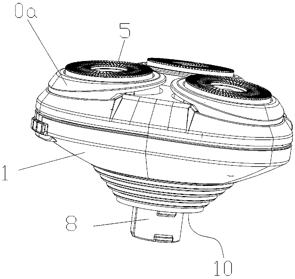
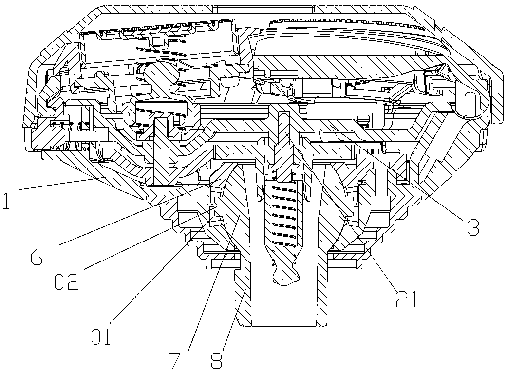
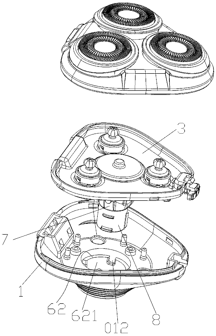
[0026] Embodiment 1: as Figure 1-7 As shown, a shaver head structure includes a housing 1, a driving gear 22 arranged in the housing 1 and a driven gear 42 meshing with the driving gear 22, and the housing 1 is also provided with There is a fixed plate 3, the outer edge of the fixed plate 3 matches the inner wall of the housing 1, and can be fixed with the housing 1 by clamping, and the driving gear 22 and the driven gear 42 pass through the driving gear shaft 21 respectively. and the driven gear shaft 41 are installed on the same side of the fixed plate 3, the driven gear shaft 41 is connected with the shaving assembly 5, the upper part of the housing 1 is connected with the upper cover body 0a, the shaving assembly 5 It is arranged on the upper cover body 0a, and the number of shaving assemblies 5 is at least three, and the space between the driving gear 22 and the bottom of the housing 1 is provided with a ball hinge seat 6 and the ball The hinged ball head 7 connected to...

Embodiment 2

[0034] Embodiment 2: a shaver, including a shaver head, and the shaver head is the shaver head with the structure in Embodiment 1.


PUM


Abstract

The invention discloses a shaver head structure. The structure comprises a shell, a driving gear arranged in the shell and a driven gear meshed with the driving gear, a fixing plate is further arranged in the shell, and the driving gear and the driven gear are arranged on the same side of the fixing plate through a driving gear shaft and a driven gear shaft respectively; and the structure is characterized in that a space between the driving gear and the bottom of the shell is internally provided with a ball hinge seat, a hinge ball head connected with the ball hinge seat, and a machine body connecting part which is connected with the hinge ball head, extends out of the shell and is used for being connected with a shaver machine body, wherein the ball hinge seat is fixedly arranged on the shell. According to the structure and a shaver, the structural strength is good, the service life is long, the shaving experience is good, the assembly is convenient, and the manufacturing cost is greatly reduced.

Description

technical field [0001] The invention relates to the field of personal care appliances, in particular to a shaver head structure and a shaver. Background technique [0002] In the prior art, in order to ensure a better shaving experience between the knife net and the facial contour, the knife head on which the knife net is set must be floating. [0003] Generally, the coordination between the spherical floating support with spherical concave and the floating support plate with spherical support is set in the cutter head housing to realize the floating of the cutter head, such as a spherical floating bracket published by the application number CN201410750358.6 In this patent, the arrangement of the spherical concave position and the spherical support is not very reasonable. The spherical concave position and the spherical support are located in the area between the driving gear and the floating support plate, so that the spherical support has an overall The problem of small s...

Claims


Application Information

Patent Timeline
Patent Type & Authority Applications(China)
IPC IPC(8): B26B19/14
CPCB26B19/146
Inventor 李高艳
Owner ZHEJIANG ZHIBO ELECTRICAL APPLIANCE TECH CO LTD
Learn More