Line width compensation method and system for 3D printing of buildings

A compensation method, 3D printer technology, applied in ceramic molding machines, manufacturing tools, additive processing, etc., can solve the problems of lack of feedback adjustment, the accuracy of printed components is difficult to meet the design requirements, etc., to achieve real-time detection, real-time printing, and improve accuracy Effect

Active Publication Date: 2019-09-27
CHINA CONSTR EIGHT ENG DIV CORP LTD
View PDF10 Cites 12 Cited by
  • Summary
  • Abstract
  • Description
  • Claims
  • Application Information

AI Technical Summary

Problems solved by technology

[0005] The purpose of the present invention is to overcome the defects of the prior art, provide a method and system for building 3D printing line width compensation, and solve the problem that the existing 3D printer process lacks feedback adjustment, which makes it difficult for the obtained printed components to meet the design requirements in terms of accuracy.

Method used


Image

  • Line width compensation method and system for 3D printing of buildings
  • Line width compensation method and system for 3D printing of buildings

Examples


Embodiment Construction

[0038] The present invention will be further described below in conjunction with the accompanying drawings and specific embodiments.

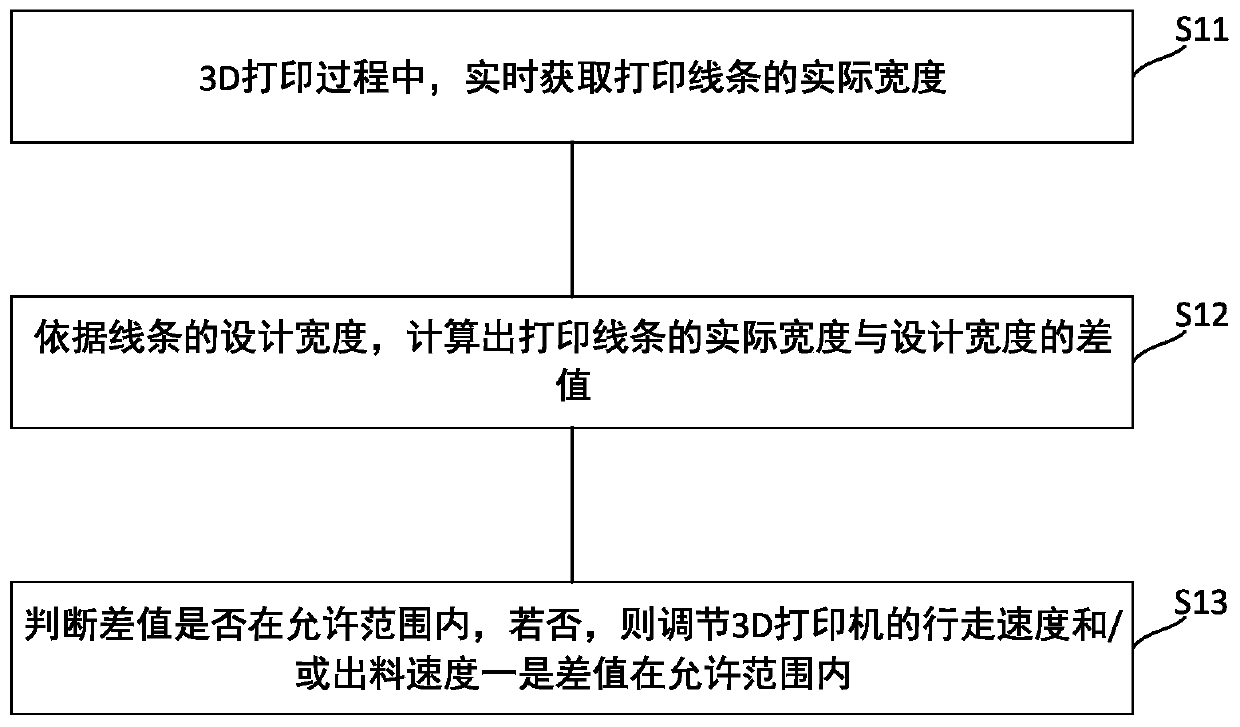
[0039] refer to figure 1 , the present invention provides a method and system for compensating the line width of architectural 3D printing, which is used to improve the printing accuracy, monitor the width of the printing line in real time, and adjust the 3D printer in real time according to the actual width of the printing line, so that the printing line The actual width is close to or equal to the design width, thereby ensuring the quality of the printed components. The method and system for building 3D printing line width compensation of the present invention will be described below in conjunction with the accompanying drawings.

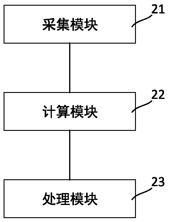
[0040] refer to figure 2 , shows the system diagram of the architectural 3D printing line width compensation system of the present invention. Combine below figure 2 , to describe the architectural 3D printing...


PUM


Abstract

The invention relates to a line width compensation method and system for 3D printing of buildings. The method includes the following steps that in the process of 3D printing, the actual width of a printed line is obtained in real time; according to the designed width of the line, a difference value between the obtained actual width of the printed line and the designed width of the line is calculated; and whether the calculated and obtained difference value is within an allowed range or not is judged, if not, a travelling speed and/or a discharging speed of a 3D printer are/is adjusted so that the difference value can be within the allowed range. According to the line width compensation method for 3D printing of the buildings, the actual width of the printed line is monitored in real time, the designed width and the actual width are compared, when the difference value of the designed width and the actual width exceeds the allowed range, the travelling speed and/or the discharging speed of the 3D printer are/is automatically adjusted so that the actual width of the 3D printed line approaches the designed width, real-time detecting is achieved, real-time printing is achieved, real-time adjusting is achieved, and therefore the quality and the precision of a component formed due to printing are improved.

Description

technical field [0001] The invention relates to the field of building construction engineering, in particular to a method and system for building 3D printing line width compensation. Background technique [0002] The material used in architectural 3D printing is cement mortar, which has a large particle size and poor fluidity. Therefore, the width of the track line during actual printing is not completely consistent with the design width and the size of the outlet. [0003] The 3D printer includes a frame and a feeder set on the frame. The frame can move along the three directions of XYZ, so that the 3D printer can move to any desired position in the three-dimensional space. The feeder is provided with a screw rod And the material outlet, through the rotation of the screw rod, the material is sent out from the material outlet and forms a printing line at the printing position. [0004] Among them, the walking speed of the frame, the rotation speed of the screw, the diameter...

Claims


Application Information

Patent Timeline
Patent Type & Authority Applications(China)
IPC IPC(8): B28B1/00B33Y10/00B33Y50/02
CPCB28B1/001B33Y10/00B33Y50/02
Inventor 韩立芳连春明杨燕王进白洁
Owner CHINA CONSTR EIGHT ENG DIV CORP LTD
Why Eureka
Try Eureka