
An injection mold with overflow blocks

A technology of injection mold and overflow material, which is applied to home appliances, other home appliances, coatings, etc., can solve the problems of edge-wrapping products such as lack of material, insufficient filling, and affecting product yield, so as to improve yield and appearance Complete and beautiful effect

Active Publication Date: 2020-07-24
FUYAO GLASS IND GROUP CO LTD
View PDF8 Cites 0 Cited by
  • Summary
  • Abstract
  • Description
  • Claims
  • Application Information

AI Technical Summary

Problems solved by technology

[0004] During the injection molding process of the above-mentioned large PU injection mold, the material flow in the mold cavity is too long. At the end of the material flow, the PU two-component isocyanate and polyol have undergone a chemical reaction and solidified, and the subsequent material flow cannot continue along the The direction of the material flow moves forward, resulting in the defects of edge-wrapping products and insufficient injection at the end of the material flow, resulting in waste products and affecting the product yield.
If the injection volume of PU is increased, for the hemming products with complex surface structures such as studs and bosses at the end of the material flow, the problem of complete hemming lack of material cannot be solved, but the amount of flash around the hemming product will be increased. Increased trimming workload in subsequent processes

Method used


Image

  • An injection mold with overflow blocks
  • An injection mold with overflow blocks
  • An injection mold with overflow blocks

Examples


Embodiment Construction

[0022] The content of the present invention will be further described below in conjunction with the accompanying drawings.

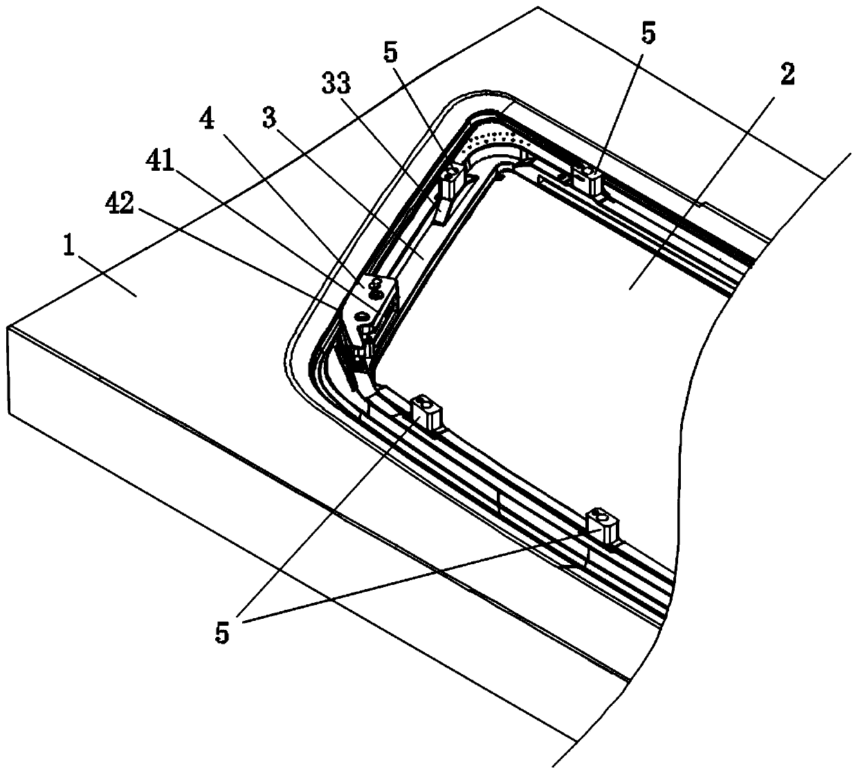
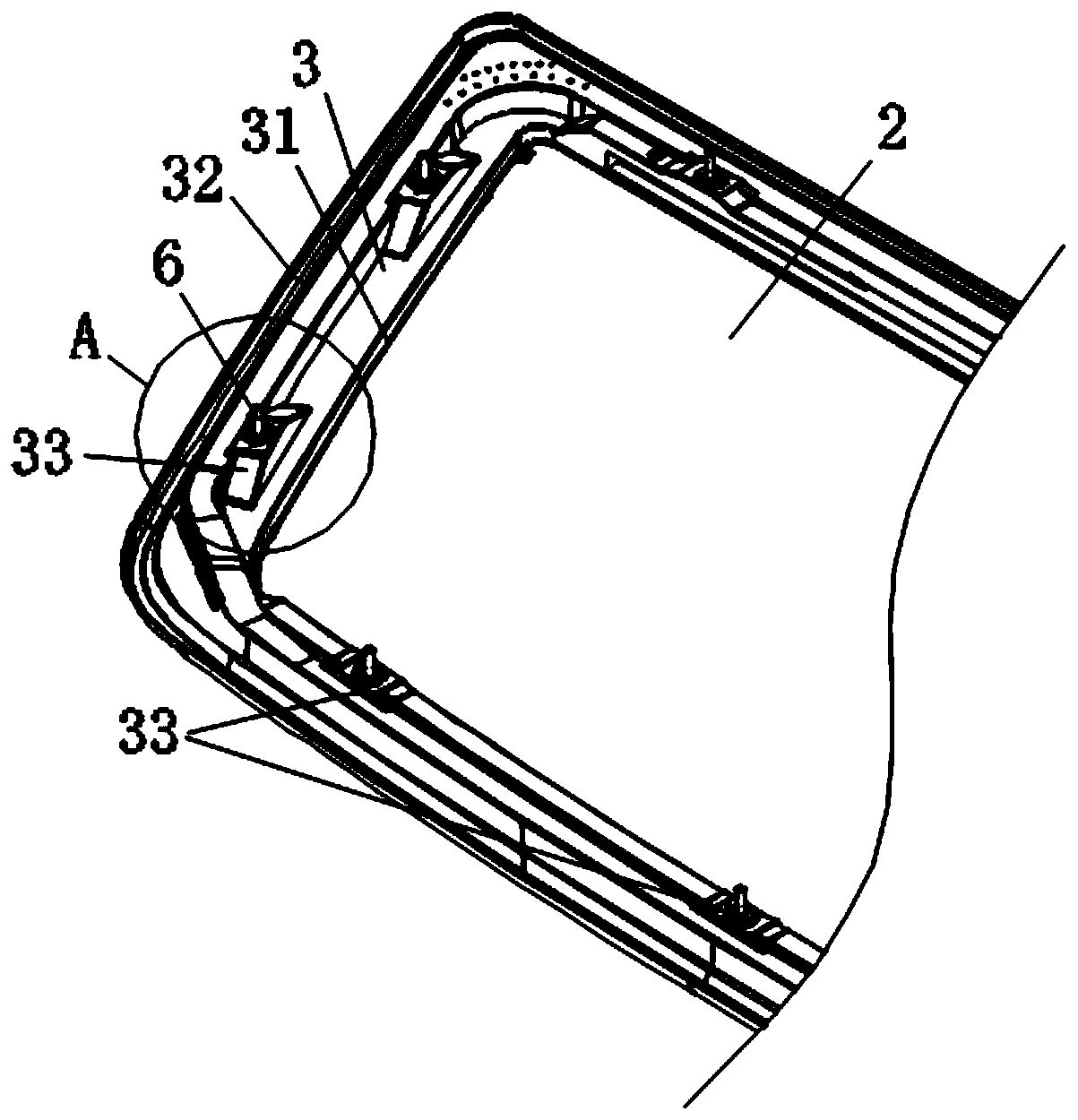
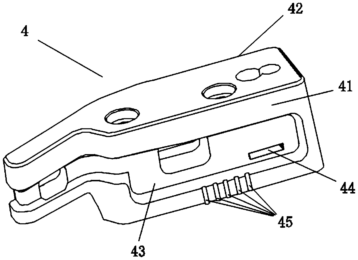
[0023] Such as Figure 1~4 As shown, an injection mold with a flash block according to the present invention includes an upper mold and a lower mold 1 used in conjunction, and the upper mold and the lower mold 1 form a mold cavity for accommodating glass 2 after mold closing body, the mold cavity includes an injection molding cavity arranged around the periphery of the glass 2, so that the injection plastic flow flows along the injection molding cavity and injects an edge strip 3 on the periphery of the glass 2, which It is characterized in that: the upper surface of the edge-wrapping strip 3 is provided with a boss 33, and the boss 33 is distributed along the circumference of the glass 2, and the boss 33 closest to the end of the material flow of the injection molding cavity Covered with an overflow block 4, the overflow block 4 is detachably installed...


PUM

PropertyMeasurementUnit
areaaaaaaaaaaa

Abstract

The invention relates to the technical field of injection molds, in particular to an injection mold with an overflow block. The injection mold comprises an upper mold and a lower mold which are matched for use; after being assembled, the upper mold and the lower mold form a mold cavity for accommodating glass; and the mold cavity comprises an injection molding cavity which is formed around the periphery of the glass, so that an injection plastic stream flows along the injection molding cavity and an edge banding strip is formed after injection molding at the periphery of the glass. The injection mold is characterized in that bosses are arranged on the upper surface of the edge banding strip and distributed along the periphery of the glass; the boss closest to the material stream end of the injection molding cavity is coated with the overflow block; the overflow block is detachably mounted below the upper mold; and a glue storage tank, a first communication hole communicating the glue storage tank with the upper surface of the boss coating the overflow block, a second communication hole communicating the glue storage tank with the inner side surface of the edge banding strip, and a third communication hole communicating the glue storage tank with the outer side surface of the edge banding strip are formed in the overflow block. The injection mold has the advantages that the appearance of an injection-molded complex edge banding product is completer and more beautiful, and the yield of the product is raised.

Description

Technical field: [0001] The invention relates to the technical field of injection molds, in particular to an injection mold with overflow blocks. Background technique: [0002] At present, the loading and positioning of the window glass wrapping assembly mainly depends on the precise positioning of the nail post on the back of the window glass product to the corresponding joint of the car body and maintains lasting reliability. In the prior art, insert injection molding is usually used to fix the stud to the window glass, that is, when the glass edging strip is injected, the nail stud is covered in the edging strip of the window glass in the form of an insert. This method has high bonding strength and fast production, and is a commonly used nail post fixing method. [0003] In the existing integrated injection molding process of the glass and the nail post, usually the glass and the nail post are respectively fixed in the mold, and then the edge-wrapping material is injecte...

Claims


Application Information

Patent Timeline
Patent Type & Authority Patents(China)
IPC IPC(8): B29C45/26B29C45/14B29L31/30
CPCB29C45/14377B29C45/14434B29C45/2669B29L2031/3052
Inventor 李裕洲高健张金泉蒋李杏陈华关金亮
Owner FUYAO GLASS IND GROUP CO LTD
Learn More