Device for unifying length of ejector sleeve

A technology of spool and push tube seat is applied in the field of devices for unifying the length of the spool and push tube, which can solve the problems of large maintenance, high comprehensive product cost, low production efficiency, etc., so as to prolong the service life, reduce the comprehensive cost, improve The effect of efficiency

Inactive Publication Date: 2019-09-27
宁海县第一注塑模具有限公司
View PDF0 Cites 0 Cited by
  • Summary
  • Abstract
  • Description
  • Claims
  • Application Information

AI Technical Summary

Problems solved by technology

[0002] Explanation: The cylinder is a standardized and standardized part of the injection mold used to form the blind hole cylindrical head structure of the product. The cylinder is composed of the cylinder core rod and the cylinder push tube; the cylinder core rod and the cylinder push tube are also respectively Referred to as the core rod and the push tube; when the push tube is used for mold manufacturing, the length of the push tube should be based on the working stroke of the mold top plate, plus the sum of the thickness of the moving mold support plate and the moving mold core, that is, the approximate height of the moving mold For selection, due to the different heights of the moving molds, the lengths of the push tubes in the prior art are different, and there are many length specifications. Many length specifications lead to high costs for mold companies to purchase and inventory backlogs, and it is difficult to identify when selecting, so it is necessary to use measuring tools , For example, using a vernier caliper and a steel ruler to select a push tube of a suitable specification from many push tubes of different specifications is labor-intensive, time-consuming and inefficient; in addition, a large mold with a high moving mold shape needs to use a long push tube. In actual operation, the long push tube is easy to break and damage, resulting in a large amount of maintenance during mold injection operation, low production efficiency, high maintenance cost, and high overall cost of products; therefore, the existing technology has many specifications, high cost, and high efficiency. Problems and deficiencies of low, easy to break

Method used


Image

  • Device for unifying length of ejector sleeve
  • Device for unifying length of ejector sleeve
  • Device for unifying length of ejector sleeve

Examples


Embodiment Construction

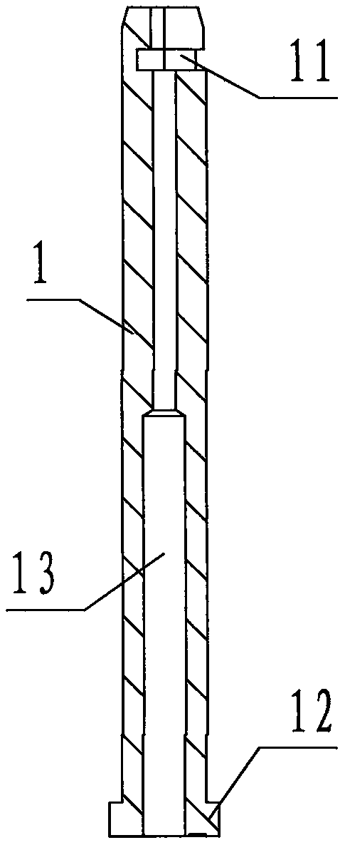
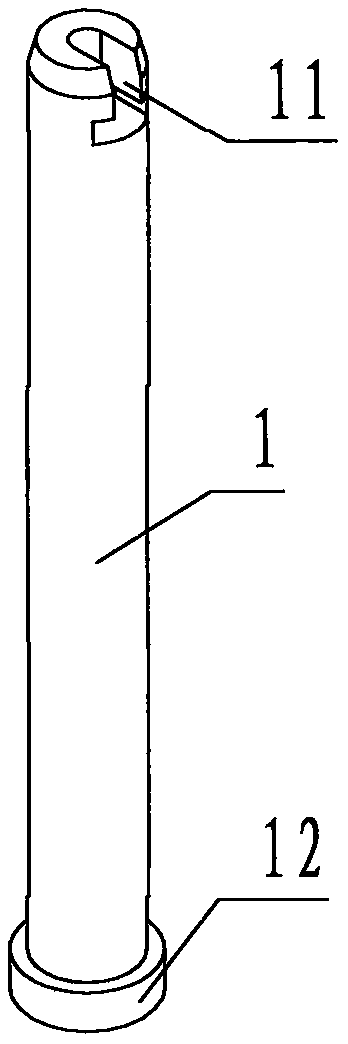
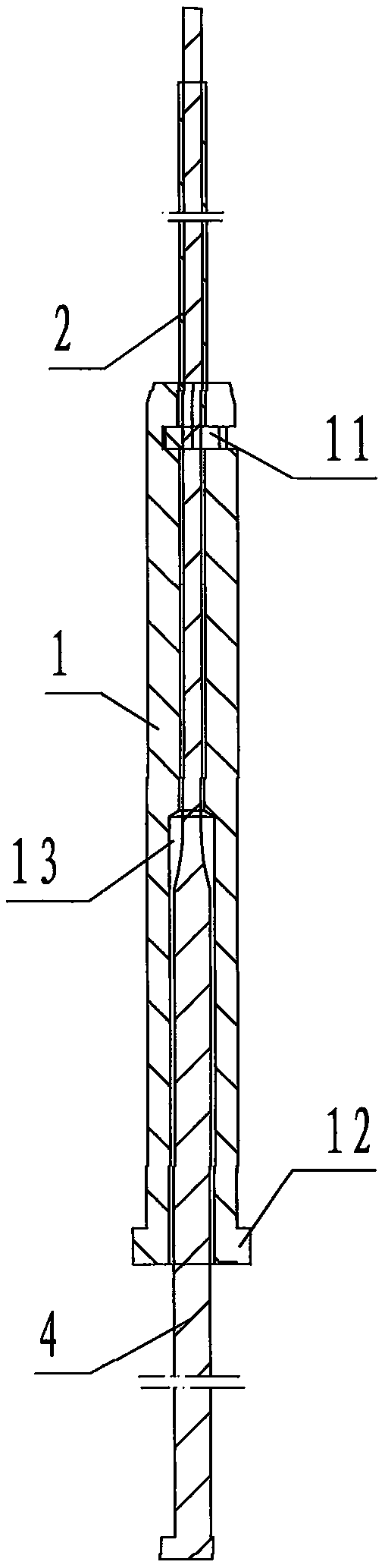
[0025] refer to Figure 1 ~ Figure 4 , a device for unifying the length of the barrel push tube of the present invention, comprising a push tube seat 1, a fixed-length push tube 2 and a tube seat sliding sleeve 3, wherein: the push tube seat 1 is a cylindrical tubular steel Components, the upper end of the push tube base 1 is provided with a connection port 11 for buckle connection to the fixed-length push tube 2, the lower end of the push tube base 1 is provided with a flange step called a seat 12, and the inner cavity of the push tube base 1 is the upper The passage of small lower big cylindrical step shape is called core slideway 13;

[0026] The fixed-length push tube 2 is a short specification push tube with a short length among many length specifications of the tube push tube in the prior art;

[0027] The tube seat sliding sleeve 3 is a cylindrical tubular steel member;

[0028] In application, there are cylindrical step holes in the upper and lower directions, small ...


PUM


Abstract

The invention discloses a device for unifying the length of of an ejector sleeve. The device comprises an ejector sleeve base, a length setting ejector sleeve and an ejector sleeve base sliding sleeve. The ejector sleeve base is provided with a connecting hole, a base table and a core slide way; the length setting ejector sleeve is a short-specification ejector sleeve in the prior art; the ejector sleeve base sliding sleeve is a cylindrical pipe-shaped steel component; during demoulding, an ejector sleeve core rod is static, a movable mold top plate pushes the ejector sleeve base and the length setting ejector sleeve upwards, and the upper end of the ejector sleeve core rod is pulled out from a blind hole cylindrical head of a product; when the device is applied to molds with different heights, the up-down position, in an ejector sleeve base receding hole, of the upper part of the ejector sleeve base is different, and the length of the length setting ejector sleeve does not need to be changed, so that the ejector sleeves with various length specifications can be unified into fixed-length ejector sleeves with a short specification; due to the fact that the length of the length setting ejector sleeve is short, the risk that the ejector sleeve in the application is easy to break is eliminated, so that for the ejector sleeve, the purposes of reducing the cost, improving the efficiency and being not prone to being broken and prolonging the service life are achieved.

Description

technical field [0001] The invention relates to a barrel part of an injection mold, in particular to a device for unifying the length of the barrel push tube. Background technique [0002] Explanation: The cylinder is a standardized and standardized part of the injection mold used to form the blind hole cylindrical head structure of the product. The cylinder is composed of the cylinder core rod and the cylinder push tube; the cylinder core rod and the cylinder push tube are also respectively Referred to as the core rod and the push tube; when the push tube is used for mold manufacturing, the length of the push tube should be based on the working stroke of the mold top plate, plus the sum of the thickness of the moving mold support plate and the moving mold core, that is, the approximate height of the moving mold For selection, due to the different heights of the moving molds, the lengths of the push tubes in the prior art are different, and there are many length specificatio...

Claims


Application Information

Patent Timeline
Patent Type & Authority Applications(China)
IPC IPC(8): B29C45/33B29C45/44
CPCB29C45/33B29C45/332B29C45/44
Inventor 施孝剑潘金博丁波
Owner 宁海县第一注塑模具有限公司
Why Eureka
Try Eureka