Strip tensioning and winding assembly

A winding group and tensioning technology, which is applied in the field of amorphous thin strip tensioning components, can solve the problem that the winding roller cannot quickly absorb and break the strip, and achieve the effects of saving loading and unloading tools, reducing damage, and simple structure

Inactive Publication Date: 2019-09-27
昌邑恒昌新材料科技有限公司
View PDF2 Cites 3 Cited by
  • Summary
  • Abstract
  • Description
  • Claims
  • Application Information

AI Technical Summary

Problems solved by technology

[0018] Aiming at the defects in the prior art, the present invention provides a strip tensioning and winding assembly, which is used to solve the problem of the inability to quickly install and disassemble the roll when the tip and the roll are matched in the traditional technology; and the roll The problem of not being able to quickly absorb the broken belt

Method used


Image

  • Strip tensioning and winding assembly
  • Strip tensioning and winding assembly
  • Strip tensioning and winding assembly

Examples


Embodiment Construction

[0039] Embodiments of the technical solutions of the present invention will be described in detail below in conjunction with the accompanying drawings. The following examples are only used to illustrate the technical solutions of the present invention more clearly, and therefore are only examples, rather than limiting the protection scope of the present invention.

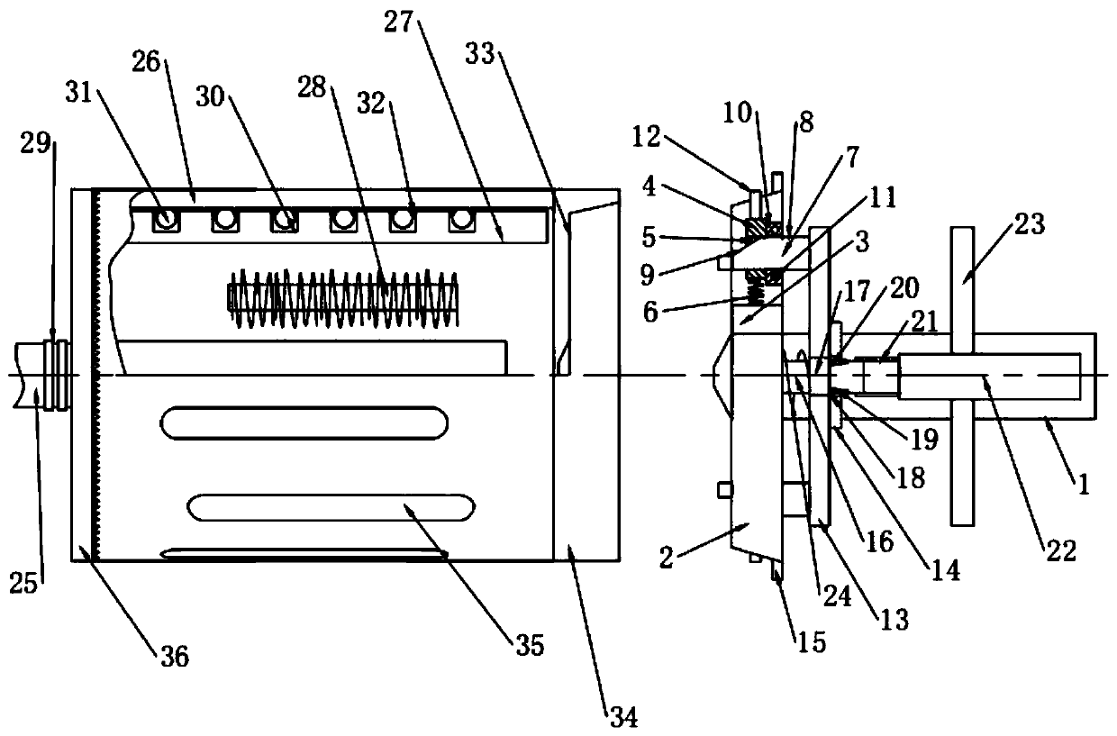
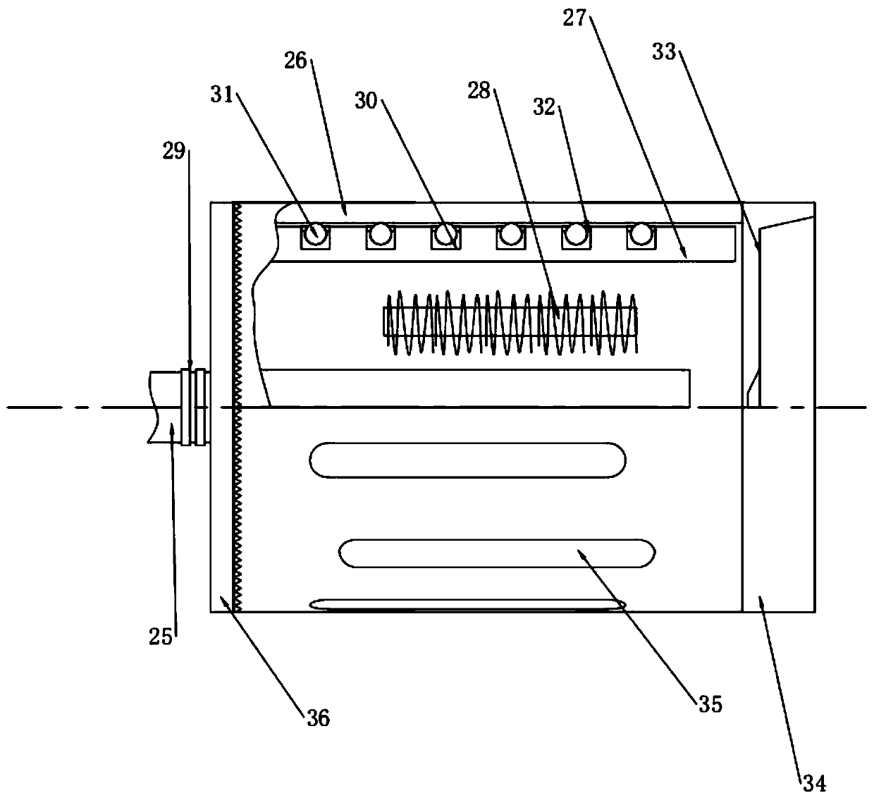
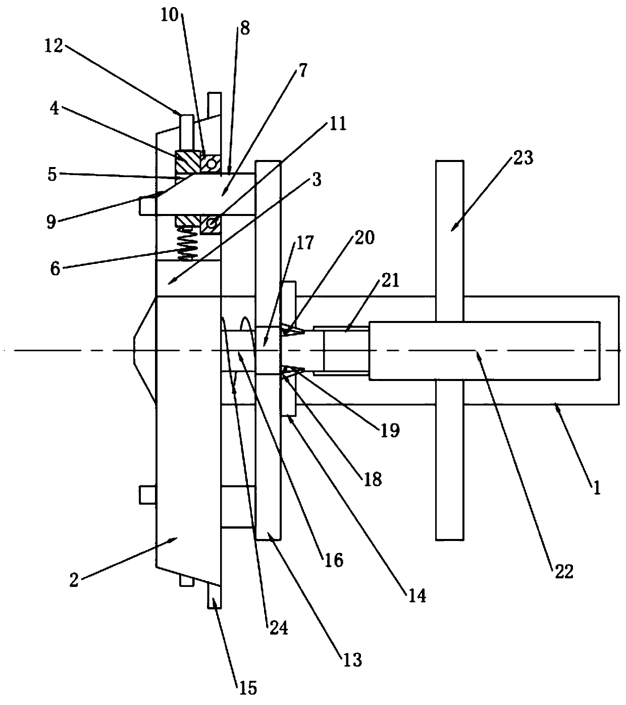
[0040] Such as Figure 1 to Figure 3 As shown, the strip tension winding assembly includes a driving roller 27, a winding roller 26, and a clamping disc 2 installed on the top 1; the clamping disc 2 performs an automatic clamping action after touching the winding roller 26, And drive the winding roller 26 to be clamped on the driving roller 27, and the driving roller 27 is equipped with a slip ring 29 and an inductance coil 28, the slip ring 29 is installed on one end of the driving roller 27, and the inductance coil 28 is surrounded by the driving roller 27. On the inner wall, the slip ring 29 is electrically con...


PUM


Abstract

The invention provides a strip tensioning and winding assembly and relates to the technical field of amorphous thin strip tensioning assemblies. The strip tensioning and winding assembly comprises a drive roller, a winding roller, and a clamping disc installed on the tip. After the clamping disc and the winding roller abut against each other, automatic clamping action is carried out, and the winding roller is driven to be installed on the drive roller in a clamped manner. A sliding ring and an inductance coil are installed on the drive roller. The sliding ring is installed at one end of the drive roller. The inductance coil is arranged on the inner wall of the drive roller in an enclosure manner. The sliding ring is electrically connected with the inductance coil. The strip tensioning and winding assembly solves the problems that when the tip is matched with the winding roller in the traditional technology, the winding roller cannot be assembled and disassembled rapidly, and the winding roller cannot adsorb broken strips rapidly.

Description

technical field [0001] The invention relates to the technical field of an amorphous thin strip tensioning component, in particular to a strip tensioning and winding component. Background technique [0002] Amorphous alloy material is a new type of alloy material that came out in the 1970s. Non-metals such as silicon, boron, and carbon are added to metals such as steel, cobalt, nickel, and chromium, and a certain proportion of steel, silicon, and Boron and other mixed hot melts are cooled at a high speed equivalent to cooling one million degrees Celsius per second. The cooling speed is 105-107K / s, and the rotation speed of the cooling chassis is about 30m / s. From the solution to the finished thin strip, it is formed at one time. , the long-range disordered structure obtained by making the alloy atoms too late to be arranged in an orderly manner, without the grains and grain boundaries of the crystalline alloy, has many unique properties, and excellent soft magnetic properties...

Claims


Application Information

Patent Timeline
Patent Type & Authority Applications(China)
IPC IPC(8): B65H18/02B65H18/10B65H19/30B65H75/28
CPCB65H18/02B65H18/10B65H19/30B65H75/28B65H2405/40B65H2701/173
Inventor 滕孝义隋建都
Owner 昌邑恒昌新材料科技有限公司
Why Eureka
Try Eureka