
Radial ripple diaphragm coupling

A corrugated diaphragm, coupling technology, used in couplings, elastic couplings, mechanical equipment, etc.

Inactive Publication Date: 2019-09-27
LUDONG UNIVERSITY
View PDF6 Cites 3 Cited by
  • Summary
  • Abstract
  • Description
  • Claims
  • Application Information

AI Technical Summary

Problems solved by technology

Utilizing the radial corrugated structure of the diaphragm itself and its strong deformation ability, the additional load acting on the diaphragm due to additional displacement is greatly reduced, the service life of the diaphragm coupling is improved, and the problems caused by design defects are solved as a whole. coming question

Method used


Image

  • Radial ripple diaphragm coupling
  • Radial ripple diaphragm coupling
  • Radial ripple diaphragm coupling

Examples


Embodiment 1

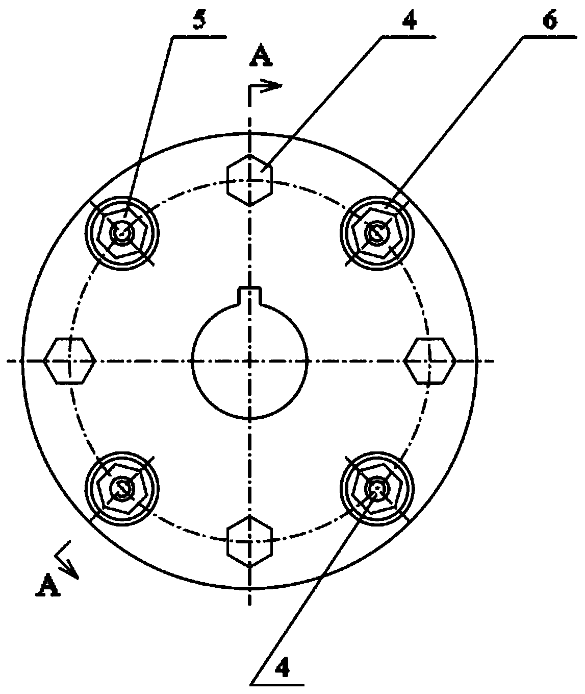
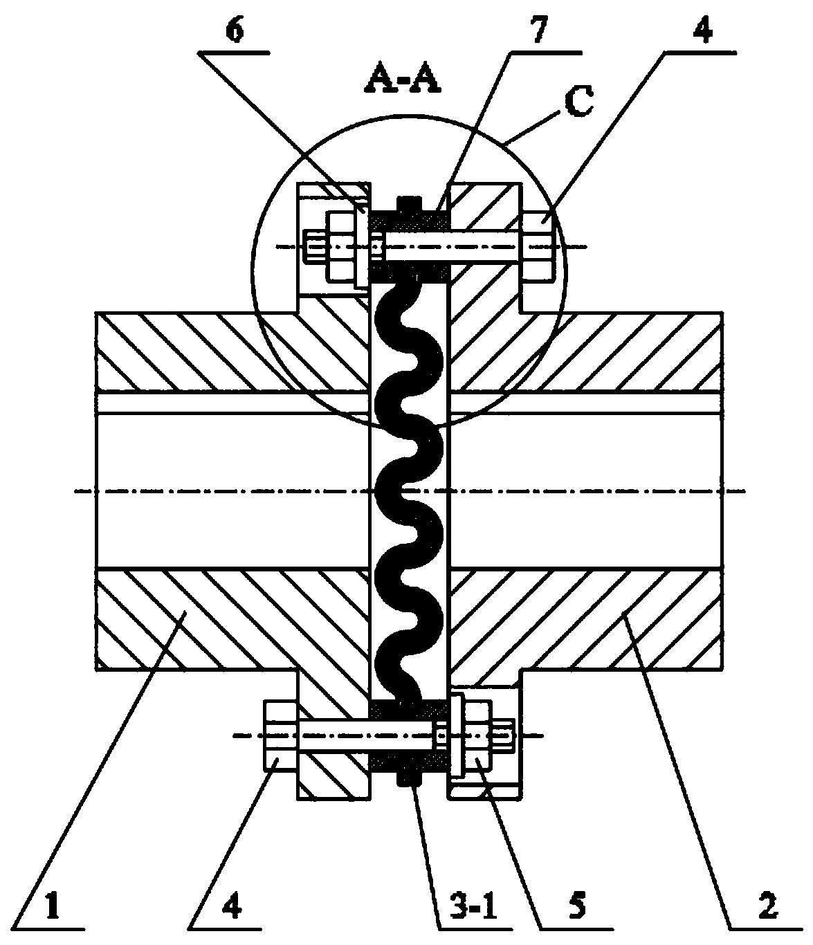
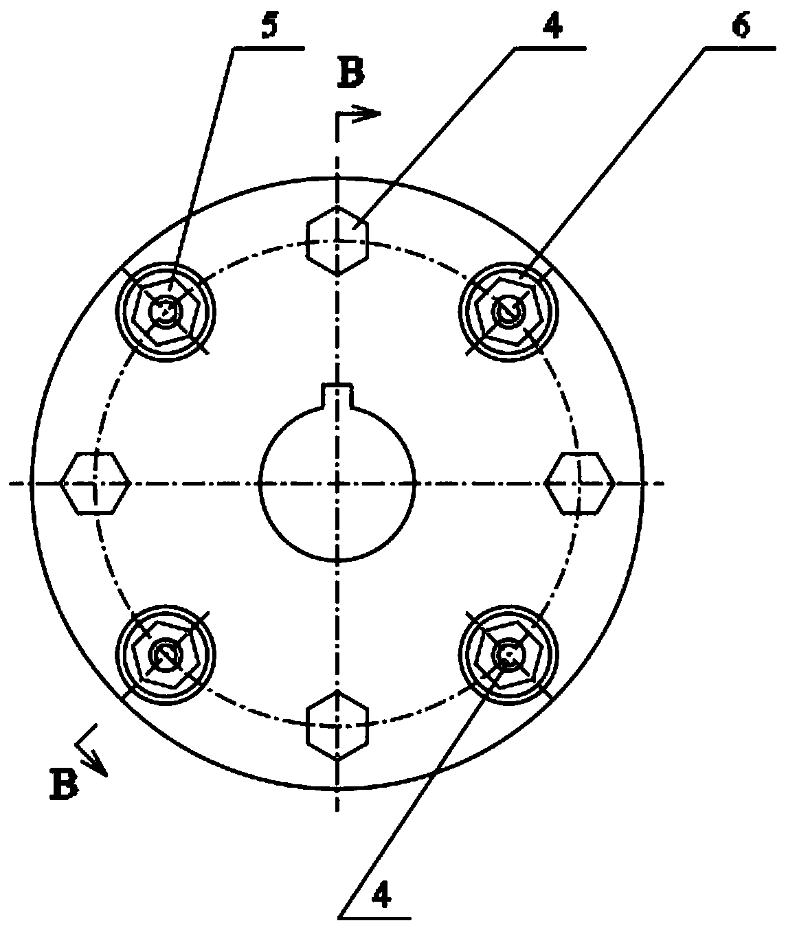
[0016] Embodiment 1, reference figure 1 , figure 2 , image 3 , Figure 4 , Figure 5 , Image 6 , Figure 7 , Figure 8 , Figure 9 , Figure 10 . It can be seen from the accompanying drawings that a radial corrugated diaphragm coupling consists of a first half coupling 1, a second half coupling 2, a radial corrugated diaphragm group 3, and a diaphragm group connecting bolt 4 , Diaphragm group connecting bolts and nuts 5, Diaphragm group connecting bolt gasket 6, Diaphragm group fixing sleeve 7; It is characterized in that the radial corrugated diaphragm group 3 passes through the diaphragm group connecting bolt 4, the diaphragm group connecting bolt The nut 5, the diaphragm group connecting bolt gasket 6, and the diaphragm group fixing sleeve 7 are connected to the first half coupling 1 and the second half coupling 2 respectively. The radially corrugated diaphragm group 3 is divided into two structures: a diaphragm group 3-1 without a mesopore structure and a dia...


PUM


Abstract

The invention discloses a radial ripple diaphragm coupling. Since a diaphragm coupling of an existing structure fails to adapt to large angular displacement, axial displacement and radial displacement, particularly to large radial displacement, the application range of the coupling is limited; or the diaphragm coupling fails to effectively reduce a load attached to a diaphragm due to appendant displacement, and the usability and the service life of the coupling are directly influenced. To solve the problems, a diaphragm of a radial ripple structure is invented. Since the diaphragm is of the ripple structure and has the good rigidity for transmitting movement and power as well as having the good elasticity for achieving compensation of large axial displacement, radial displacement and angular displacement.

Description

technical field [0001] The invention relates to a coupling of a mechanical transmission device, which is a coupling device for movement and power transmission between a prime mover (such as an electric motor, an internal combustion engine, etc.) and a working machine (such as a pump, a reducer, etc.), and belongs to the technical field of mechanical transmission . Background technique [0002] Couplings are widely used in rotating machinery, including rigid couplings and elastic couplings. Diaphragm coupling is a new type of coupling, which has the advantages of transmitting large torque, allowing large displacement error, allowing high-speed rotation, mitigating impact vibration, generally does not need lubrication, and is easy to install and maintain. It is widely used in National defense, shipbuilding, aviation, petrochemical, vehicles, machinery and other industries can replace gear couplings, elastic sleeve pin couplings and other coupling devices. However, due to the...

Claims


Application Information

Patent Timeline
Patent Type & Authority Applications(China)
IPC IPC(8): F16D3/56
CPCF16D3/56
Inventor 王亮申陈燕王昕彦田忠民王晓晨
Owner LUDONG UNIVERSITY
Learn More