A gas storage wellbore and cavity sealing method and device
A technology for sealing detection and gas storage, which is applied in the direction of using liquid/vacuum degree for liquid tightness measurement and measuring the acceleration and deceleration rate of fluid, etc., can solve problems such as lack of technology, improve detection efficiency and shorten detection time. , the effect of reducing the space filled with gas
- Summary
- Abstract
- Description
- Claims
- Application Information
AI Technical Summary
Problems solved by technology
Method used
Image
Examples
Embodiment 1
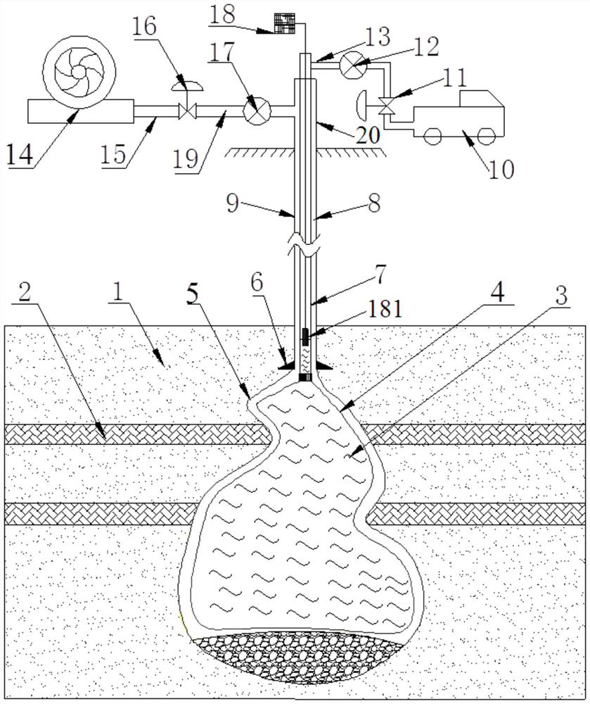
[0061] see figure 1 , in an embodiment of the present invention, a method for detecting the airtightness of a gas storage wellbore and cavity, comprising the following steps:
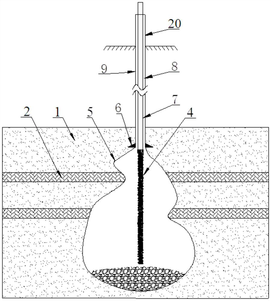
[0062] (1) A retractable air bag 4 is set in the cavity 5 of the gas storage, and the air bag 4 is communicated with the liquid outlet end of the infusion pipeline 7, and the infusion pipeline 7 stretches into the well shaft 9 of the gas storage (the sleeve of the gas storage) Pipe shoe 6 or more parts), such as figure 2 shown;
[0063] In this embodiment, the connection between the infusion pipeline 7 and the air bag 4 is located at the top of the chamber body 5 of the gas storage, so that after the air bag is fully filled, the shaft 9 of the gas storage will not be blocked, and the air bag fills the gas storage as much as possible. Cavity 5 spaces.
[0064] (2) Inject liquid 3 into the airbag 4 through the infusion pipeline 7, inject gas 19 into the annular space 8 between the wellbore 9 and the i...
Embodiment 2
[0100] Based on the same inventive concept, this embodiment provides a device for implementing the above gas storage wellbore and cavity airtightness detection method, see figure 1 , the device includes: air bag 4, infusion pipeline 7, liquid supply equipment 10, liquid supply pipeline 13, gas supply equipment 14, gas supply pipeline 15, air-water interface measurement equipment 18 and infusion wellhead 20, wherein:
[0101] The air bag 4 is installed at the outlet of the infusion pipeline 7, and is communicated with the infusion pipeline 7 by a connector. When testing, the air bag 4 is positioned in the cavity 5 of the gas storage, as figure 2 shown.
[0102] The infusion pipeline 7 communicates with the liquid supply equipment 10 through the liquid supply pipeline 13. When testing, the infusion pipeline 7 extends into the well shaft 9 of the gas storage, and the connection between the infusion pipeline 7 and the air bag 4 is located at the top of the cavity 5 ,Such as fi...
PUM
 Abstract
Description
Claims
Application Information
 - R&D
- Intellectual Property
- Life Sciences
- Materials
- Tech Scout
- Unparalleled Data Quality
- Higher Quality Content
- 60% Fewer Hallucinations
Browse by: Latest US Patents, China's latest patents, Technical Efficacy Thesaurus, Application Domain, Technology Topic, Popular Technical Reports.
© 2025 PatSnap. All rights reserved.Legal|Privacy policy|Modern Slavery Act Transparency Statement|Sitemap|About US| Contact US: help@patsnap.com


