Automatic wire pulling machine for transformer

A transformer and automatic technology, applied in the manufacture of inductors/transformers/magnets, electrical components, circuits, etc., can solve the problems of poor products, low production efficiency, high labor intensity, etc., to improve production efficiency, ensure good rate, and reduce labor. The effect of labor intensity and labor cost

Pending Publication Date: 2019-09-27
DONGGUAN JIALONG HAIJIE ELECTRONICS TECH CO LTD
View PDF0 Cites 3 Cited by
  • Summary
  • Abstract
  • Description
  • Claims
  • Application Information

AI Technical Summary

Problems solved by technology

[0003] In view of this, the present invention aims at the deficiencies in the prior art, and its main purpose is to provide an automatic wire pulling machine for transformers, which effectively solves the problems of poor products, high labor intensity and low production efficiency caused by the existing manual pulling of wire ends. low problem

Method used


Image

  • Automatic wire pulling machine for transformer
  • Automatic wire pulling machine for transformer
  • Automatic wire pulling machine for transformer

Examples


Embodiment Construction

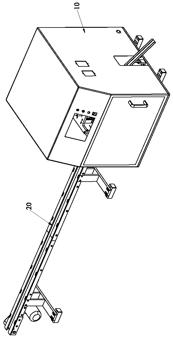
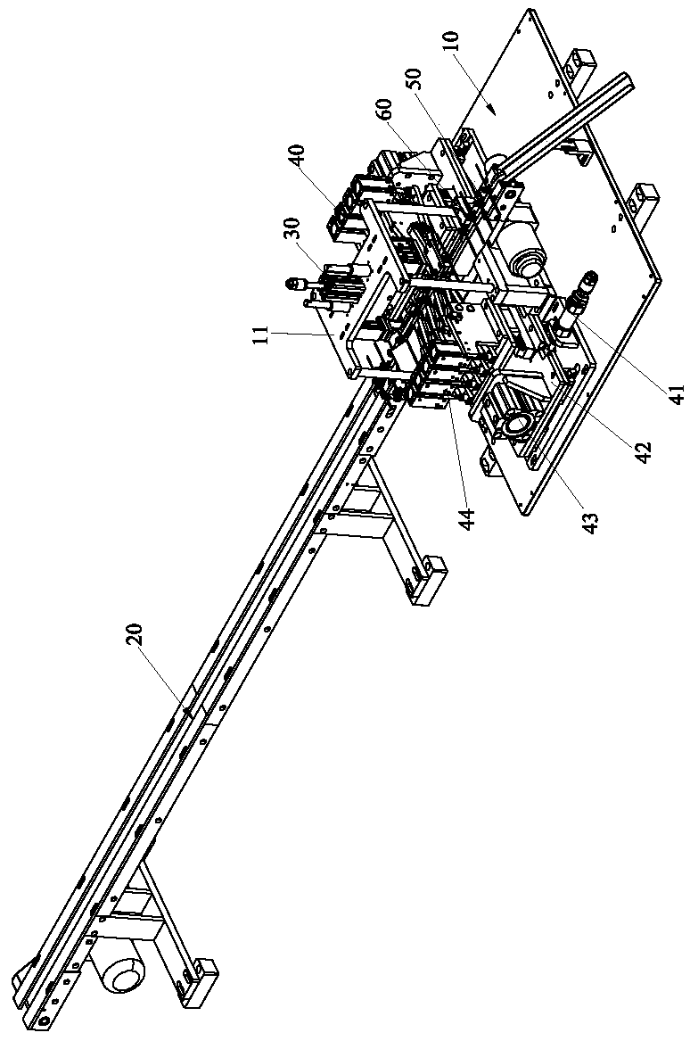
[0044] Please refer to Figure 1 to Figure 7 As shown, it shows the specific structure of the preferred embodiment of the present invention, including a frame 10, a control mechanism (not shown in the figure), a conveying mechanism 20, a jig fixing mechanism 30, a wire pulling mechanism 40 and a transformer control mechanism. Tool 50.

[0045] The control mechanism is arranged on the frame 10 . The conveying mechanism 20 is arranged on the frame 10 and is electrically connected with the control mechanism. In this embodiment, the conveying mechanism 20 is a structure in which a motor drives a belt to rotate. The conveying mechanism 20 is provided with a photoelectric sensor switch (not shown in the figure) for sensing the position of the transformer jig.

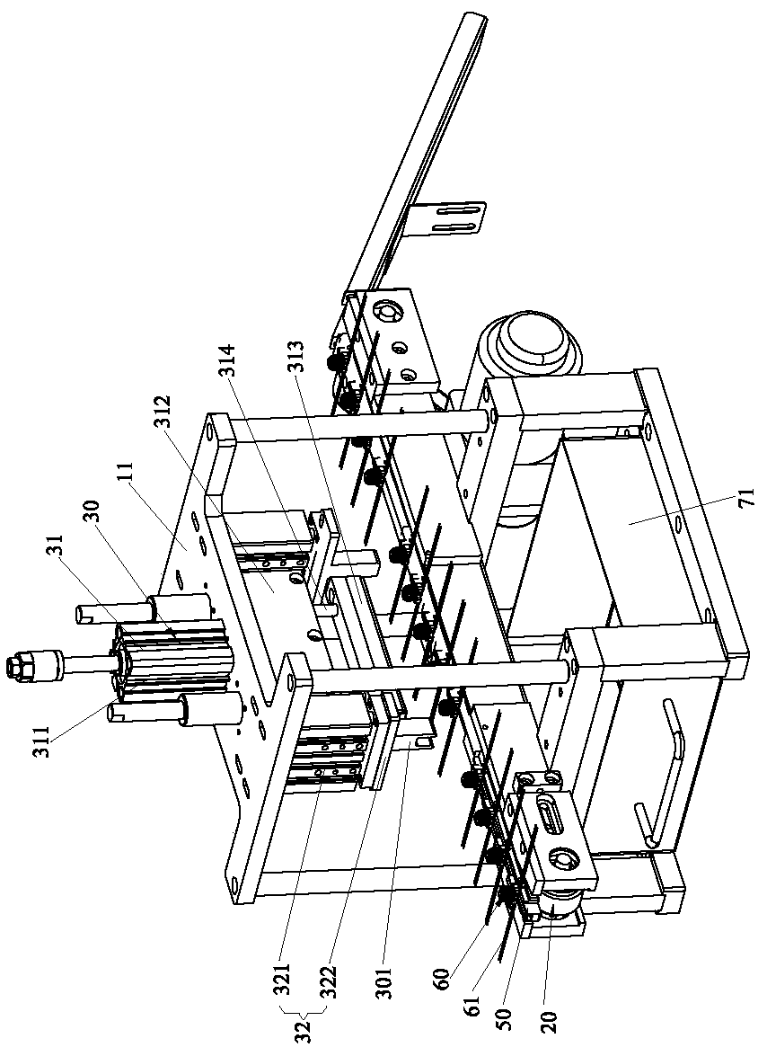
[0046] The jig fixing mechanism 30 is arranged on the frame 10 and directly above the conveying mechanism 20 , and the jig fixing mechanism 30 is electrically connected with the control mechanism. The jig fixing mechanism ...


PUM


Abstract

The invention discloses an automatic wire pulling machine for a transformer. The automatic wire pulling machine comprises a frame, a control mechanism, a conveying mechanism, a jig fixing mechanism, a wire pulling mechanism and a transformer jig. The jig fixing mechanism is arranged on the frame and located over the conveying mechanism. The wire pulling mechanism is arranged on the frame and located beside the jig fixing mechanism. The wire pulling mechanism comprises a first driving device, a movable frame, a second driving device and a wire head clamping device. The transformer jig is placed on the conveying mechanism, a plurality of transformer mounting stations are arranged on the top surface of the transformer jig, and a blade part used for cutting a wire head is formed at the corner of the top surface of the transformer jig. Through the integrated arrangement of the control mechanism, the conveying mechanism, the jig fixing mechanism and the wire pulling mechanism and the cooperative use of the transformer jig, the automatic wire pulling machine achieves the automatic conveying, fixing and wire pulling of a transformer. Compared with traditional manual wire pulling, the automatic wire pulling machine achieves the mechanical wire pulling, guarantees the excellent rate of products, reduces the labor intensity of workers and the labor cost, and improves the production efficiency.

Description

technical field [0001] The invention relates to the technology in the field of transformer production machinery automation, in particular to an automatic wire pulling machine for transformers. Background technique [0002] During the processing of the transformer, both ends of the copper wire must be hung on the PIN pin, and a certain amount of flying wires must be reserved at both ends to ensure good contact between the coil and the PIN pin. After the copper wire is wound twice on the PIN pin, it is necessary to tear off the excess flying wire. The process of tearing off the flying wire ends is mostly manual work. After putting the product into the jig, clamp the flying wire ends with pliers to tear them off. Such operations are not easy to control the strength and direction of the wire pulling, which may easily cause defective products; and the labor intensity is high, and the production efficiency is low. Contents of the invention [0003] In view of this, the present...

Claims


Application Information

Patent Timeline
Patent Type & Authority Applications(China)
IPC IPC(8): H01F41/00H01F41/076
CPCH01F41/00H01F41/076
Inventor 阮诗扬叶棣中程波王健
Owner DONGGUAN JIALONG HAIJIE ELECTRONICS TECH CO LTD
Why Eureka
Try Eureka