Microelectromechanical sensor

一种微机电传感器、电性的技术,应用在传感器领域,能够解决调节瞬间高压作用不足等问题,达到提升可靠度与使用灵敏度、改善损坏情况的效果

Active Publication Date: 2019-09-27
MERRY ELECTRONICS (SHENZHEN) CO LTD
View PDF11 Cites 5 Cited by
  • Summary
  • Abstract
  • Description
  • Claims
  • Application Information

AI Technical Summary

Problems solved by technology

[0003] However, considering that adding a pressure relief hole may affect the elasticity of the diaphragm and the sensing performance of the sensor, only a small amount of pressure relief holes with a small area can be added without affecting the sensing effect, which can adjust the effect of instantaneous high pressure Relatively insufficient
Therefore, the existing technical means using pressure relief holes still cannot avoid the possibility of damage to the diaphragm caused by pressure differences

Method used


Image

  • Microelectromechanical sensor
  • Microelectromechanical sensor
  • Microelectromechanical sensor

Examples


Embodiment Construction

[0034] In order to facilitate the understanding of the present invention, the present invention will be described more fully below with reference to the associated drawings. Preferred embodiments of the invention are shown in the accompanying drawings. However, the present invention can be embodied in many different forms and is not limited to the embodiments described herein. On the contrary, these embodiments are provided to make the understanding of the disclosure of the present invention more thorough and comprehensive.

[0035] Unless otherwise defined, all technical and scientific terms used herein have the same meaning as commonly understood by one of ordinary skill in the technical field of the invention. The terminology used herein in the description of the present invention is only for the purpose of describing specific embodiments, and is not intended to limit the present invention.

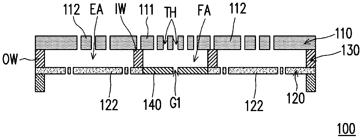
[0036] figure 1 is a schematic cross-sectional view of a MEMS sensor according ...


PUM


Abstract

The invention relates to a microelectromechanical sensor comprising an electrode plate, a vibrating diaphragm structure, a supporting structure and a pressure releasing film layer. The electrode plate has a conductive portion. The vibrating diaphragm structure is spaced apart on one side of the electrode plate and has a sensing film layer. The supporting structure is disposed between the vibrating diaphragm structure and the electrode plate and surrounds an electrical coupling region and a gas flow region. The supporting structure includes an inner wall and an outer wall. The inner wall surrounds the outer edge of the gas flow zone, and the outer wall surrounds the outer edge of the electrical coupling zone. The pressure releasing film layer blocks the gas flow zone.

Description

technical field [0001] The invention relates to the field of sensors, in particular to a micro-electromechanical sensor. Background technique [0002] The vibrating membrane of the MEMS sensor may be damaged by the strong wind in the environment or the instantaneous high pressure generated by the air squeezed by the door panel. Nowadays, in order to avoid the excessive pressure difference inside and outside the MEMS sensor, multiple pressure relief holes are added to the vibrating membrane of the sensor. When the inside and outside of the sensor are subjected to large air pressure changes, multiple pressure relief holes can Adjust the pressure balance inside and outside the sensor. [0003] However, considering that adding a pressure relief hole may affect the elasticity of the diaphragm and the sensing performance of the sensor, only a small amount of pressure relief holes with a small area can be added without affecting the sensing effect, which can adjust the effect of i...

Claims


Application Information

Patent Timeline
Patent Type & Authority Applications(China)
IPC IPC(8): H04R19/00H04R19/02H04R31/00
CPCH04R19/005H04R19/02H04R31/003B81B7/0029B81B2201/0257B81B2201/0264H04R7/06H04R19/04B81B3/0021B81B7/007B81B2203/0127B81B2203/04G01N27/227H04R11/04
Inventor 蒋铠宇陈振颐张朝森
Owner MERRY ELECTRONICS (SHENZHEN) CO LTD
Why Eureka
Try Eureka