Automatic analyzer and cleaning mechanism in automatic analyzer
A technology of automatic analysis device and cleaning mechanism, which is applied in the direction of analyzing materials, cleaning hollow objects, and containers used in laboratories, etc., and can solve problems affecting analysis results, etc.
- Summary
- Abstract
- Description
- Claims
- Application Information
AI Technical Summary
Problems solved by technology
Method used
Image
Examples
Embodiment 1
[0033]
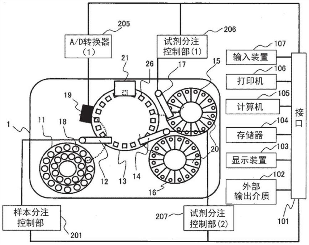
[0034] figure 1 It is a figure which shows the basic structure of the automatic analysis apparatus concerning this embodiment. Here, an example of a turntable type biochemical analyzer will be described as one form of an automatic analyzer.
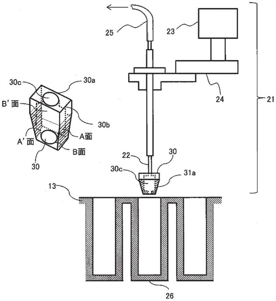
[0035] As shown in this figure, the housing of the automatic analyzer 1 is equipped with: a reaction disk 13 , a sample disk 11 , a first reagent disk 15 , a second reagent disk 16 , a photometer 19 , and a cleaning mechanism 21 .
[0036] The reaction disk 13 is a disk-shaped unit that can freely rotate clockwise and counterclockwise, and a plurality of reaction vessels 26 can be arranged on the circumference of the reaction disk 13 .
[0037] The sample disk 11 is a disk-shaped unit that can freely rotate clockwise or counterclockwise, and a plurality of sample containers 18 for storing biological samples such as standard samples or test samples can be arranged on the circumference of the sample disk 11 .
[0038] The first...
Embodiment 2
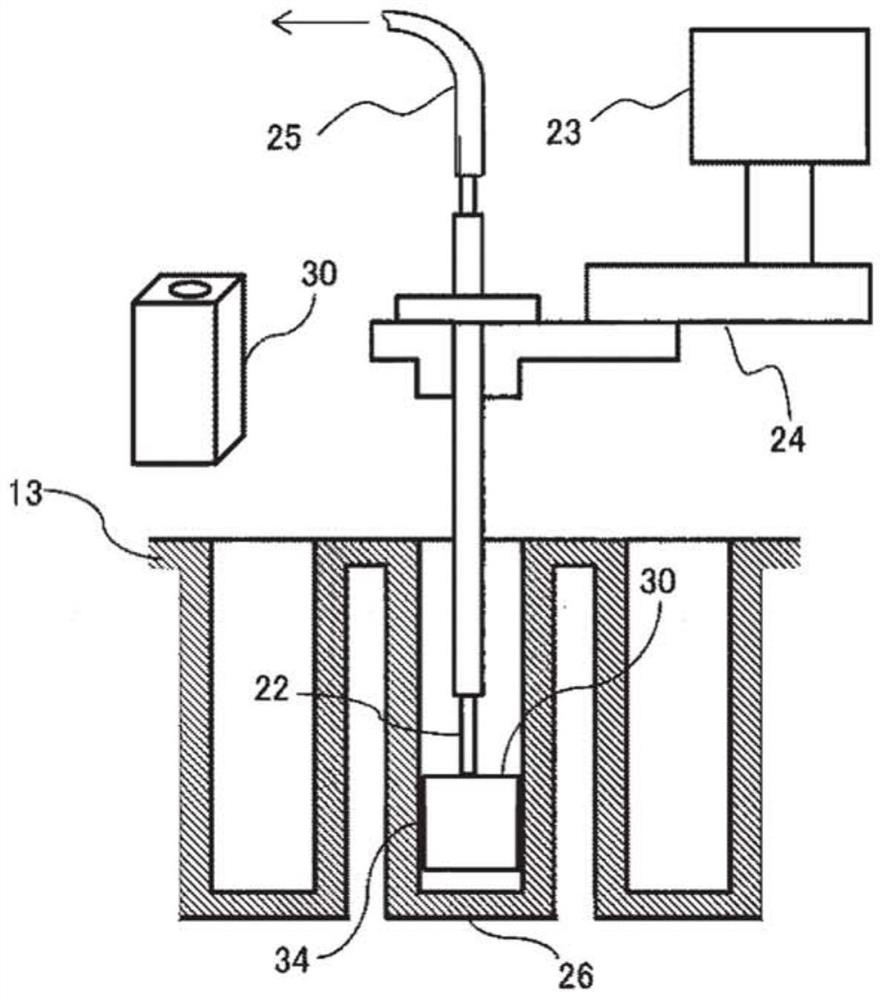
[0077] Next, another configuration of the cleaning mechanism 21 of the automatic analyzer 1 according to the present embodiment will be described. In the first embodiment described above, the case where the height of the cleaning head 30 is lower than the height of the reaction vessel 26 (the height from the opening (upper end) to the bottom (lower end)) is illustrated and described. here, use Figure 6 A structure in which the height of the cleaning head 30 is approximately the same as the height from the opening of the reaction container 26 to the bottom surface, and the tapered body 31 a is provided from the upper end to the lower end of the cleaning head 30 will be described. Figure 6 It is a figure which shows the structure of the cleaning mechanism provided with the cleaning head concerning this embodiment (Example 2). In addition, in this figure, with Figure 4 same, shown from relative to figure 2 The diagram is viewed from an angle where the right side of the rea...
Embodiment 3
[0081] Next, another configuration of the reaction vessel 26 of the automatic analyzer 1 according to the present embodiment will be described. In the above-mentioned embodiment, the structure of the reaction vessel 26 using a rectangular parallelepiped on all sides has been described. Here, the Figure 7 The case of using a reaction vessel (hereinafter referred to as a conical reaction vessel 33) formed as a part of the reaction vessel, that is, in a state where the lower end of the cleaning head 30 is in contact with the bottom surface, is described. In the cuboid region 33a (first region) from the position of the upper end of 30 to the bottom surface of the reaction vessel, the cross-sectional area of the plane perpendicular to the insertion direction of the cleaning head 30 into the reaction vessel is equal; from the upper end of the cleaning head 30 to the reaction vessel In the tapered region 33b (second region) up to the opening, the cross-sectional area of the surf...
PUM
 Abstract
Description
Claims
Application Information
 - R&D
- Intellectual Property
- Life Sciences
- Materials
- Tech Scout
- Unparalleled Data Quality
- Higher Quality Content
- 60% Fewer Hallucinations
Browse by: Latest US Patents, China's latest patents, Technical Efficacy Thesaurus, Application Domain, Technology Topic, Popular Technical Reports.
© 2025 PatSnap. All rights reserved.Legal|Privacy policy|Modern Slavery Act Transparency Statement|Sitemap|About US| Contact US: help@patsnap.com


