
Forming milling cutter provided with spiral flute

A technology for forming milling cutters and chip removal grooves, which is applied in milling cutters, milling machine equipment, manufacturing tools, etc. The effect of direct rigid collision, prolonging service life and improving machining accuracy

Inactive Publication Date: 2019-10-01
常州昊美工具有限公司
View PDF0 Cites 0 Cited by
  • Summary
  • Abstract
  • Description
  • Claims
  • Application Information

AI Technical Summary

Problems solved by technology

[0003] Although forming milling cutters are widely used now, there are still some problems in the actual use process. First, the existing forming milling cutters have defects in processing waste chips, and waste chips are easy to remain on the surface of the milling cutters. And the follow-up processing is troublesome, and it is easy to cause the bluntness of the milling cutter. Second, the existing forming milling cutter will generate a large amount of vibration to the handle when it is working, which will easily cause damage to the handle and affect the machining accuracy and the service life of the milling cutter. Third, when the existing forming milling cutter is working, miscellaneous chips will fly randomly, which will not only affect the processing accuracy of the product, but also affect the normal rotation of the milling cutter, increasing the difficulty of processing

Method used


Image

  • Forming milling cutter provided with spiral flute
  • Forming milling cutter provided with spiral flute
  • Forming milling cutter provided with spiral flute

Examples


Embodiment Construction

[0016] The following will clearly and completely describe the technical solutions in the embodiments of the present invention with reference to the accompanying drawings in the embodiments of the present invention. Obviously, the described embodiments are only some, not all, embodiments of the present invention. Based on the embodiments of the present invention, all other embodiments obtained by persons of ordinary skill in the art without making creative efforts belong to the protection scope of the present invention.

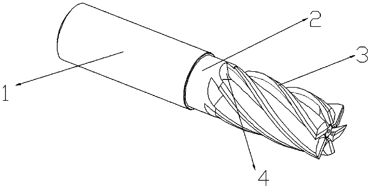
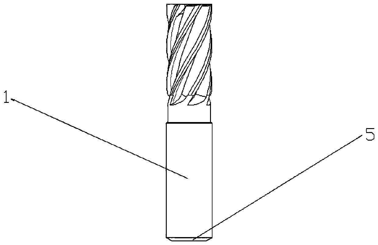
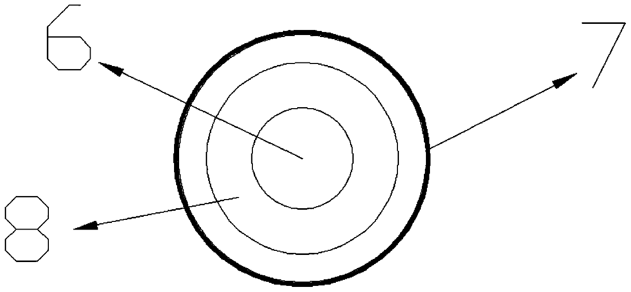
[0017] see Figure 1~4 , a forming milling cutter with a spiral flute, comprising a tool handle outer casing 1, a cutter bar 2, a blade 3, a spiral flute 4, a shock-absorbing rubber ring 5, a connecting hole 6, a brush 7, a knife Shank middle compartment 8, ventilation hole 9 and force column 10; said knife handle outer cover 1 is arranged on the outer surface of the knife handle in a cylindrical cavity structure, and said knife rod 2 is fixed on the knife han...


PUM


Abstract

The invention discloses a forming milling cutter provided with a spiral flute. The forming milling cutter provided with the spiral flute comprises an outer cutter handle housing, a cutter rod, a blade, the spiral flute, a rubber damping ring, a connecting hole, a brush, an intermediate interlayer of a cutter handle, a ventilating hole and a stressing column. The forming milling cutter provided with the spiral flute has the beneficial effects that the outer cutter handle housing is capable of certainly protecting the surface of the cutter handle, and thus residual chippings in the spiral flutecan be removed conveniently after processing; the chippings can downwards fly out along the spiral radian through the spiral flute while the forming milling cutter is used for processing, so that thechippings are prevented from flying everywhere, and moreover, the safety of the processing environment is ensured; the vibration to the forming milling cutter in work can be reduced through the rubberdamping ring, and thus the service life of the forming milling cutter is prolonged; in addition, the cutter handle is prevented from being in direct rigid collision with a connector; the intermediateinterlayer of the cutter handle enables uniform downwards discharging of the chippings of the forming milling cutter in work; air which is downwards blown is produced by rotating air current througha through hole, and thus the processing accuracy is effectively improved.

Description

technical field [0001] The invention relates to a milling cutter, in particular to a forming milling cutter with a spiral flute, and belongs to the technical field of forming milling cutters. Background technique [0002] Forming milling cutters are designed according to the profile of the workpiece. Forming milling cutters can be used to process complex-shaped surfaces on general-purpose milling machines, and obtain high processing accuracy and surface finish quality requirements, which can effectively improve the efficiency of production products. , Forming milling cutters are often used to process workpieces such as forming straight grooves, forming spiral grooves and other special-shaped grooves. [0003] Although forming milling cutters are widely used now, there are still some problems in the actual use process. First, the existing forming milling cutters have defects in processing waste chips, and waste chips are easy to remain on the surface of the milling cutters. ...

Claims


Application Information

Patent Timeline
Patent Type & Authority Applications(China)
IPC IPC(8): B23C5/10B23C5/00B23C5/16
CPCB23C5/003B23C5/1081B23C5/16B23C2210/40
Inventor 蒋卫
Owner 常州昊美工具有限公司
Learn More