Thick plate laser cutting method

A laser cutting, laser beam technology, applied in laser welding equipment, welding equipment, metal processing equipment and other directions, can solve the problem of cutting can not continue, molten metal reverse spray, etc., to reduce laser power and shielding gas consumption, reduce The effect of high running cost and cutting rate

Active Publication Date: 2019-10-01
CHANGSHA UNIVERSITY OF SCIENCE AND TECHNOLOGY
View PDF17 Cites 2 Cited by
  • Summary
  • Abstract
  • Description
  • Claims
  • Application Information

AI Technical Summary

Problems solved by technology

[0006] The purpose of the present invention is to solve the problem that the molten metal appears in the corner of the laser cutting thick plate and "reverse spraying" occurs upwards, so that the cutting cannot continue

Method used


Image

  • Thick plate laser cutting method
  • Thick plate laser cutting method
  • Thick plate laser cutting method

Examples


specific Embodiment approach 2

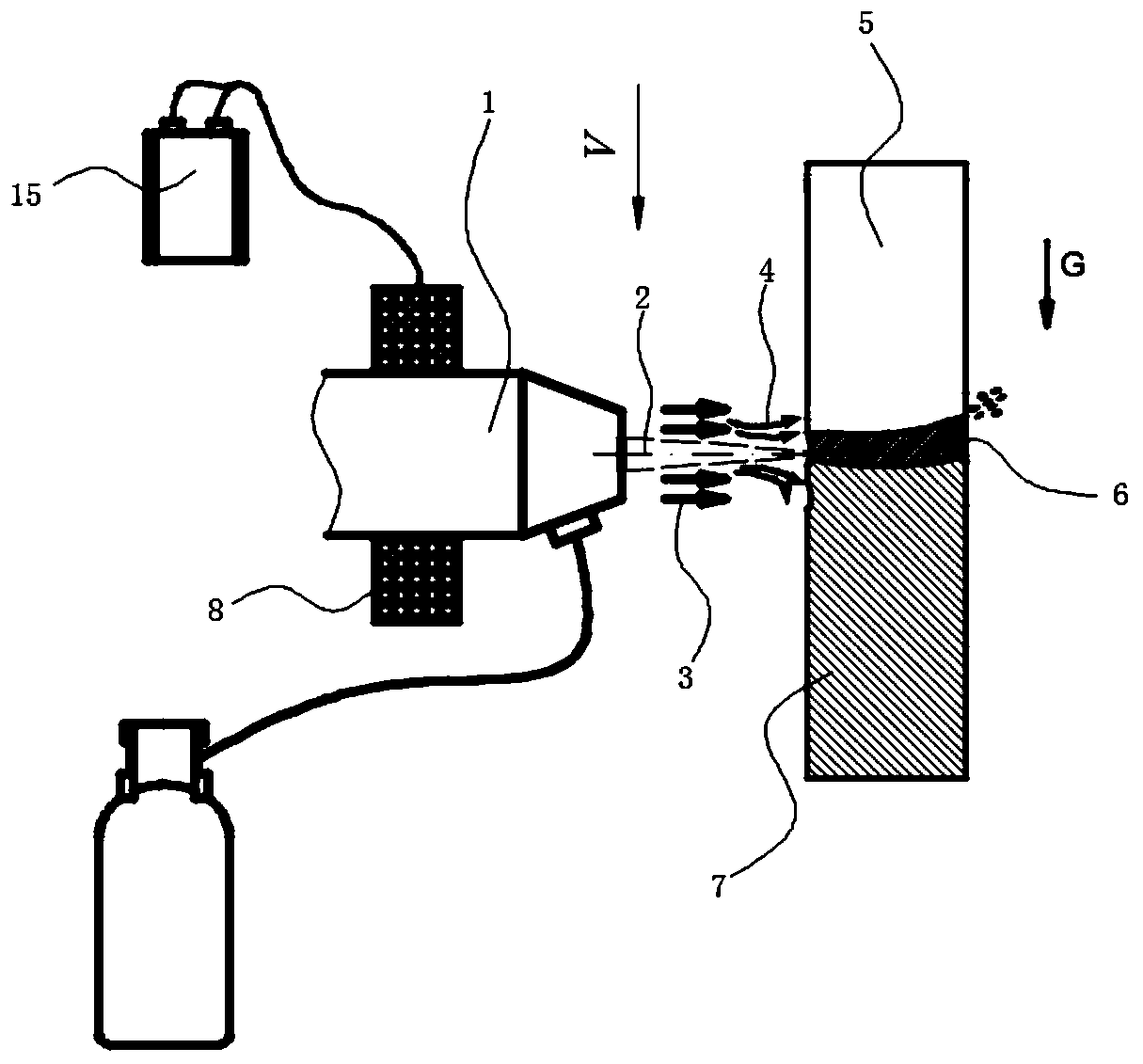
[0051] combined with Figure 5 Another embodiment of the present invention will be described in detail.

[0052] In this embodiment, the thick plate laser cutting method includes the following steps:

[0053] Step 1: Fix the electromagnetic coil 8 on the laser cutting head 1, which can move with the laser cutting head 1; in this example, the adjustable range of the electromagnetic field is 0.1~5 T.

[0054]Step 2: Place and fix the workpiece 7 to be cut vertically; in this example, the thickness of the workpiece 7 to be cut is 15-30mm.

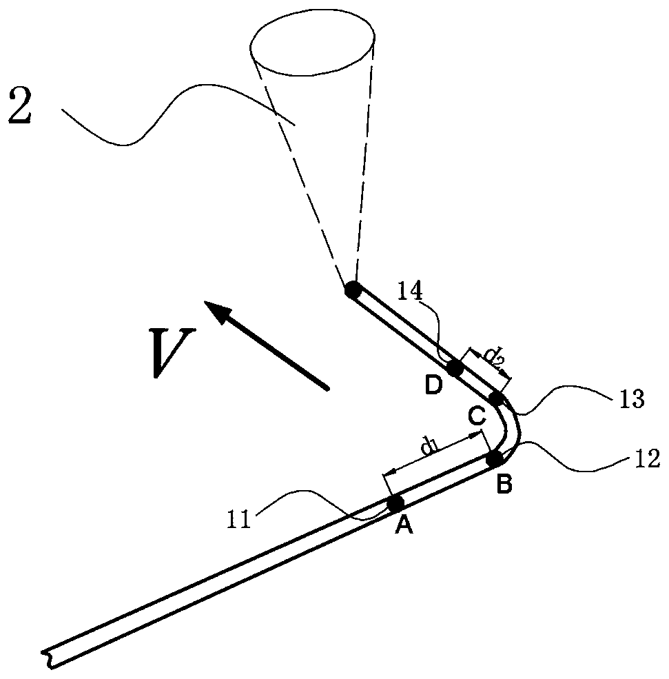
[0055] Step 3: Define the lead-in section and lead-out section of corner cutting in the laser cutting track; in this example, the corner form of the workpiece to be cut is a straight line intersection corner, and the lead-in section of corner cutting is a straight line cutting area 11 away from the starting point of the corner, and its length is d 1 is 10~30 mm, and the lead-out section of corner cutting is a section of straight cutting area...


PUM

PropertyMeasurementUnit
thicknessaaaaaaaaaa

Abstract

The invention relates to a thick plate laser cutting method. The thick plate laser cutting method is characterized by comprising the following steps of 1, fixing an electromagnetic coil onto a laser cutting head, wherein the electromagnetic coil can move along with the laser cutting head; 2, vertically placing and fixing a workpiece to be cut; 3, defining a corner cutting leading-in section and aleading-out section in a laser cutting track; 4, activating a laser cutting system, cutting auxiliary gas and an electromagnetic field power source, perpendicularly irradiating the surface of the workpiece to be cut by laser beams to realize laser cutting of a thick plate; 5, adjusting the electromagnetic field power source when the laser beams move to a starting point of the corner cutting leading-in section to start corner region cutting; 6, adjusting the electromagnetic field power source when the laser beams move to an end point of the corner cutting leading-out section to finish corner region cutting; and 7, turning off a laser generator, the electromagnetic field power source and the cutting auxiliary gas to complete the cutting process when a cutting tail end point is reached. Compared with the prior art, the thick plate laser cutting method is good in cutting effect.

Description

technical field [0001] The invention relates to a laser cutting method, in particular to a thick plate laser cutting method. Background technique [0002] At present, laser cutting technology has been widely used in sheet metal processing, metallurgical equipment, construction machinery, precision accessories, craft gifts, household appliances and many other fields. At present, the traditional laser cutting metal mainly uses the optical system in the cutting head to converge on the surface of the material to melt it, and provides auxiliary gas to blow off the melted material to achieve cutting. However, when fiber laser is used to cut thick stainless steel plates, the laser energy is intensively accumulated at the corners, which may easily cause the phenomenon of "reverse spraying" at the corners, resulting in the inability to cut. [0003] Published on May 07, 2014, the publication number is "CN 103771694 A", and the invention patent titled "Laser Cutting Method and Cuttin...

Claims


Application Information

Patent Timeline
Patent Type & Authority Applications(China)
IPC IPC(8): B23K26/38B23K26/12B23K26/70
CPCB23K26/123B23K26/38B23K26/70
Inventor 戴家辉张明军陈顺吴杰曹太山李清河
Owner CHANGSHA UNIVERSITY OF SCIENCE AND TECHNOLOGY
Why Eureka
Try Eureka